Level and Pressure Operating Instructions VEGACOM 557 Profibus FMS PC BA on 557 in out
Contents Safety information Note Ex area Please read this manual carefully, and also take note of country-specific installation standards (e.g. the VDE regulations in Germany) as well as all prevailing safety regulations and accident prevention rules. Please note the approval documents (yellow binder), and especially the included safety data sheet.
Contents Contents Safety information ........................................................................ 2 Note Ex area ................................................................................ 2 1 Product description 1.1 Function and configuration .................................................. 4 1.2 Measuring system with digital communication .................. 6 1.3 Type label and order code .................................................. 7 1.2 Type plate .............................
Product description 1 Product description VEGACOM 557 is an interface converter for conversion of VEGA specific protocols of DISBUS and LOGBUS into standard data formats. The existing version of VEGACOM 557 is used to convert data into the PROFIBUS FMS data format (FMS = Fieldbus Message Specification). As a peripheral device (Slave), the instrument can be connected to a PROFIBUS data line. The bus access is realised according to the Master-Slave procedure, enabling the master (e.g.
Product description The data set is transferred from this buffer memory into a process image. The protocol conversion software enquires the stored data cyclically from the individual storage areas. The data sets are checked and converted into the PROFIBUS data format. After the conversion, the data are transferred into emission memory and are sent from there to the PROFIBUS. The PROFIBUS transmits the data to the PROFIBUS master, loading them via a special connection component.
Product description Complete measuring system with digital communication and networking DISBUS on % 100 - ESC % 100 + - OK ESC CONNECT ! % 100 + - OK ESC CONNECT ! on - ESC - ESC - ESC ! 513 % 100 + - OK ESC CONNECT ! ! on VEGAMET 513 + OK CONNECT on VEGAMET VEGAMET 513 % 100 + OK CONNECT on on VEGAMET 513 + OK CONNECT ! on VEGAMET 513 % 100 % 100 + OK CONNECT ! on VEGAMET 513 - ESC ! on VEGAMET % 100 + OK CONNECT VEGAMET 513 513 Profi
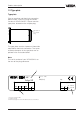
Product description 1.2 Type plate Type plate Prior to mounting and electrical connection, please check if you are using the correct version of VEGACOM 557. Please note the type plate, located on the multiple plug. Type plate on the multiple plug The type plate contains important information required for electrical connection. The layout and data elements of the type plate are explained in the illustration below. Note: The serial number of your VEGACOM is on the rear of the plug connector.
Product description 1.3 Technical data Technical data Power supply Supply voltage Power consumption Fuse Unom = 24 V AC (20 … 53 V), 50/60 Hz or = 24 V DC (20 … 72 V) approx. 6 VA 1 A, slow-blow Electrical connection Component Module in carrier BGT 596 or BGT LOG 571 Housing type 505 multiple plug acc. to DIN 41 612, series F 48-pole (d, b, z) with coding holes suitable multipoint connector acc. to DIN 41 612 with connection via standard technologies via screw terminals max. 1 x 1.
Product description PROFIBUS interface Standards conformity Interface standard Network topology Number of stations per segment - without repeater 1) - with repeater Max. bus length - without repeater - cable A - cable B - with repeater Connection cable Transmission Transmission rate 3) Coding system Number of bits Parity Data backup to DIN 19 245, part 1 and part 2 to pr EN 50 170 acc.
Product description CE conformity VEGACOM 557 meets the protective regulations of EMC (89/336/EWG) and NSR (73/23/EWG). Conformity has been judged acc. to the following standards: EMC Emission EN 50081-1 Susceptibility EN 50082-2 NSR EN 61010 Mechanical data Series module unit for - carrier BGT 596 - carrier BGT LOG 571 - housing type 505 W = 25.4 mm (5 TE), H = 128.4 mm, D = 166 mm approx.
Mounting and electrical connection 2 Mounting and electrical connection 2.1 Mounting instructions The gateway VEGACOM 557 can process measurement data and status information in two different ways: - via DISBUS (from measuring systems with VEGAMET) - via LOGBUS (from measuring systems with VEGALOG).
Mounting and electrical connection 2.2 Mounting into carrier and housing BGT 596 or BGT LOG 571 For mounting, a slot module must be provided at the requested location. A slot module consists of: - a multipoint connector acc. to DIN 41 612, series F, 33-pole (d, b, z) - two screws - three coded pins - two guide rails. The multipoint connector is available in the following versions: - Wire-Wrap, standard connection 1.0 mm x 1.0 mm - plug connection 2.8 mm x 0.8 mm - Termi-Point standard connection 1.
Mounting and electrical connection Connection via modem For remote parameter setting, it is possible to connect the PC interface via a modem. In such a case, the modem cable that comes with the respective modem should be used. Modem operation is supported by VEGACOM 557 from software version 2.11. Further information on remote parameter setting is stated in the operating instructions "Remote parameter adjustment". 2.
Mounting and electrical connection Pin assignments VEGACOM 557AP Pin-no. 1 2 3 4 5 6 7 8 9 RS 485 DATA (RxD/TxD-P) GND (DGND) /DATA (RxD/TxD-N) - 9-pole SUB-D plug Pin-no. 1 2 3 4 5 6 7 8 9 RS 485 DATA (RxD/TxD-P) GND (DGND) /DATA (RxD/TxD-N) - 9-pole SUB-D socket Mounting instructions for VEGACOM 557AP The two modules connected to the backpanel print consist of: - two multipoint connectors acc.
Mounting and electrical connection Terminals for supply voltage Ub+ Terminals for DISBUS View of back-panel board (rear of the carrier) Profibus interface of VEGACOM 557 as SUB-D plug PC interface of VEGACOM 557 PC Profibus interface of VEGACOM 557 as SUB-D socket BA on 557 557AP Front view with SUB-D connections of VEGACOM 557 and VEGACOM 557AP VEGACOM 557 Profibus FMS 15
Addressing of the process signals 3 Addressing of the process signals DIL switch, basic board 3.1 Switch adjustments on VEGACOM 557 ON EDG Factory setting For adjustment of the RS 232 PC interface in the front panel, a 6-pole DIL switch block is located on the basic board. On the additional board there are two 8-pole DIL switch blocks as well as two hook switches for termination of the bus.
Addressing of the process signals DIL switch 1, additional board Example 1 PLC VEGACOM 557 Adjustment of the baud rate Baud rate (kBit/s) S8 S7 S6 S5 S4 S3 S2 S1 9.6 off off off off off off off off 19.2 off off off off off off off on 93.75 off off off off off off on off 187.
Setup 4 Setup In this section, all measures you need to take to set up your VEGACOM 557 in conjunction with the Siemens communication processor CP5431 are described. If your PROFIBUS master is an instrument from another manufacturer, please observe the necessary measures found in the respective manufacturer documentation. In the setup procedure, the parameters of the communication processor must be set first.
Setup 6 Integrate S5 program (on diskette), which reads in measured values, into your own application - Enquire in OB21 and OB22 the functional component FB249 (SYNCHRONOUS) - Transfer data component DB240 to your own application - Initialise measured value data components (standard: DB220-235) - Transfer functional component FB210 or FB211 and/or FB212 into your own application Note: The applied functional components must be called up in every program cycle 7 Transfer components to AG 4.
Setup PROFIBUS FMS services From the point of view of the application process (S5 program), the communication system represents a group of services, the so-called FMS services. Each slave must provide duty services or can provide additional optional services.
Setup Communication reference KR A communication relationship is addressed by a local short designation, the communication reference KR. Several communication relationships can be created by the master. Local and external Service Access Point LSAP For communication, several service access points are available on both sides. In the KBL, the points where the messages pass must be explicitly stated. VEGACOM 557 PROFIBUS has more than 6 Service Access Points LSAP = 0 … 5.
Setup Basic planning 1. Menu: Init –> Edit Here, the basic initialisation, i.e. the input of the communication processor type (here CP5431) and the name of the planning data base as well as the file names for documentation output, is carried out.
Setup Basis-SSNR: - The basic interface number is required exclusively for SIMATIC components. Sectors of 4 interfaces are always reserved (adjustment range: 0, 4, 8 … 254) Number of interf.: - This parameter indicates how many interfaces (tiles) are accessed (adjustment range: 1 … 4) Module size: - Information on the storage capacity of the storage module. In addition, the generation date and the system identification can be saved.
Setup Number of external active stations: - Number of active stations not acquired in the topology file. This adjustment is necessary for the calculation of the bus parameter block. Max. participant address (HSA): - This is the highest bus address of an active bus participant. Baud rate: - The baud rate of the transmission speed. Default SAP: - On receipt of a telegram without Destinations-SAP number, the CP dials the Default SAP. No.
Setup 4. Menu: Network –> Network survey The network survey shows all database files belonging to a network and thus knots, in a list. SINEC-NCM (END) Network - Network survey ———————————————————————————————————————— No. of stations : 1 max. participant address (HSA) : 31 knot name / Data base file L2-address Type 13 CP5431 QMESSW F PAGE + 1 PAGE + F PAGE 2 PAGE - F 3 Source: C:MESSWNCM.NET F 4 F 5 DELETE F 6 F F HELP 7 TAKE OVER 8 CHOICE 5.
Setup The data are actualized with function key F7. SINEC-NCM (END) Network - Network adjustment ———————————————————————————————————————— F 1 Network data file : C : MESSWNCM.NET Destination data file : Algorithm : STANDARD F 2 F 3 F 4 F 5 F 6 F F HELP 7 TAKE OVER 8 CHOICE FMS planning During FMS planning, the communication relationship list KBL is defined.
Setup Unconfirmed orders: - This field remains empty as this is reserved for the service "Indicate variable" and this is no Gateway function. Local LSAP: - The Service Access Point (SAP) for the CP5431. With MSAZ (Master-Slave acyclical) connections this value is set automatically to the Poll-SAP 58. Strange LSAP: - This is the SAP from VEGACOM 557 Gateway. The values 0 … 5 are permitted. Strange L2 address: - The instrument address of VEGACOM 557 Gateway.
Setup Transmission of the data base to CP Menu: Load –> CP data base transfer –> FD-CP If the CP parameter setting is finished, the data base must be transferred to the communication processor: - provide connection PC/programming device with CP5431 - stop CP with "Load –> CP Stop" - transfer parameter data base to the CP: Load –> CP data base transfer –> FD-CP - set CP to operating condition with "Load –> CP Start" Important: The new data base is only active after switching off the voltage supply of the CP
Setup Dat administration: Bit 4: Data acceptance running Bit 5: Data transfer being effected Bit 6: Data acceptance being effected Bit 7: Disable data block Failure message: 0: No failure 1: Wrong type information in the functional component 2: Storage area not available 3: Storage area too small 4: Delayed acknowledgement 5: Failure in the indication word 6: Invalid source/destination parameters A: Connection error B: Handshake error C:System error D:Blocked data block E: Order cannot be processed F: Conne
Setup FB245: RECEIVE component The functional component FB245 gives a receive order to the CP. A difference is made between the orders RECEIVE and RECEIVE_ALL. With RECEIVE_ALL (A-NR is 0) receipt data of individual emission orders are received and the order RECEIVE_ALL is recommended here to read in measured values. The information in which data component the received data should be saved, was provided previously with the transmission order. Therefore no further parameters are necessary for RECEIVE_ALL.
Setup FB249: SYNCHRONOUS component By calling up this component, the AG-CP interface is initialised. Here the max. block size is stated, which can be exchanged between AG and CP when calling up a functional component. In this case, the block size must be 5 (BLGR=5: 256 Byte block size). FB249 must be called up in the organisation components OB21 and OB22.
Setup Measured values from DISBUS On DISBUS up to 15 bus participants can be connected, whereby each DISBUS participant provides less than 16 measured values (between 4 and 7 measured values). The bus addresses 1 … 15 must be configured on the VEGAMET instruments. Bus address 0 is not permitted, i.e. the measured values are between the second measured value block (for VEGAMET with bus address 1) and measured value block 16 (VEGAMET with bus address 15).
Setup DB240: Basic settings In this DB, the basic settings and order blocks for CP5431 are determined. Here, only the Start-target DB (data word 0) may be modified. All other parameters may not be modified. Start-target DB: - By this, when using FB210 (read in all measured values) the first data component for saving the measured values can be stated. Since 16 measured value blocks are read in, 16 data components must be reserved by the Start-target DB.
Setup Saving of measured values blocks in measured value data components For saving the measured values, the data components DB220 to DB235 are set as a standard feature. The Start data component can be set in DB240 in DW0 (standard: 220). The next 16 data components must be reserved for the measured values.
Setup Assignment list Menu: Editor –> Assignment list (F7 key) The functional components FB210 and FB212 require operating variables (marker words). Symbolic words were assigned to these variables, so that the index word address can be modified easily if the stated index words (MW10 and MW 252) are already used in your application. Seq. Datei: C:MESSW_Z0.SEQ Zeile: 1 Operand Symbol comment MW 10 MW_BLKNO meas.
Setup FB210: Read in all measured values With this functional component, all 256 measured values (16 measured value blocks) are read in. Important information: The interface number and the order number must be adapted to your application if necessary. These values relate to the values set in the CP connection planning. Call: The functional component must be called up in every program cycle.
Setup Listing FB 210 Network 1 Name :R-MW-ALL C:MESSW@ST.S5D LAE=93 Blatt 1 0000 000A :A DB 240 000C : 000E :O M 0.0 0010 :ON M 0.0 0012 :SPA FB 247 0014 Name :CONTROL 0016 SSNR : KY 0,0 0018 A-NR : KY 0,1 001A ANZW : MW 2 001C PAFE : MB 255 001E : 0020 :U M 3.
Setup FB 210 C:MESSW@ST.S5D 0076 QANF : KF +20 0078 QLAE : KF +15 007A PAFE : MB 255 007C : 007E : 0080 : 0082 : 0084 : 0086 : 0088 : 008A : 008C : 008E : 0090 : 0092 REC :O M 0.0 0094 :ON M 0.0 0096 :SPA FB 245 0098 Name :RECEIVE 009A SSNR : KY 0,0 009C A-NR : KY 0,0 009E ANZW : MW 2 00A0 ZTYP : KC NN 00A2 DBNR : KY 0,0 00A4 ZANF : KF +0 00A6 ZLAE : KF +0 00A8 PAFE : MB 255 00AA : 00AC : 00AE :BE MW 10 = MW_BLKNO LAE=93 Page 2 — RECEIVE_ALL order —— Order no.=0 –> RECEIVE_ALL Meas.
Setup Listing FB 211 C:MESSW@ST.S5D LAE=114 Page 1 Network 1 0000 Name :R-MW-BLK input of meas. value block Bez :BLCK E/A/D/B/T/Z: E BI/BY/W/D: W Bez :DB E/A/D/B/T/Z: E BI/BY/W/D: W Bez :STAT E/A/D/B/T/Z: A BI/BY/W/D: W 001C : 001E : 0020 : 0022 : 0024 : 0026 : 0028 :A DB 240 002A :O M 0.0 002C :ON M 0.0 002E :SPA FB 247 0030 Name :CONTROL 0032 SSNR : KY 0,0 0034 A-NR : KY 0,1 0036 ANZW : MW 2 0038 PAFE : MB 255 003A : 003C :U M 3.
Setup 0082 :O M 0.0 0084 :ON M 0.0 0086 :SPA FB 244 0088 Name :SEND 008A SSNR : KY 0,0 008C A-NR : KY 0,1 008E ANZW : MW 2 0090 QTYP : KC DB 0092 DBNR : KY 0,240 0094 QANF : KF +20 0096 QLAE : KF +15 0098 PAFE : MB 255 009A :L KH 0000 009E :T =STAT 00A0 :SPA =REC2 00A2 : 00A4 : 00A6 REC :L KH 00FF 00AA :T =STAT 00AC : 00AE REC2 :O M 0.0 00B0 :ON M 0.
Setup FB212: Read in individual measured values With this functional component, an individual measured value is read in. Saving is done in the stated data component beginning from data word offset. Important information: The interface number and the order number must be adapted to your application, if necessary. These values relate to the values set in the CP connection planning. Call: The functional component must be called up in each program cycle.
Setup 0050 : 0052 :L =MWNR 0054 :L KH 0000 0058 :!=F 005A :SPB =ERR 005C : 005E :D 1 0060 :L KF +255 0064 :<=F 0066 :SPB =OK 0068 :SPA =ERR 006A OK : 006C : 006E :L =DB 0070 :T DW 9 0072 :L =OFFS 0074 :T DW 10 0076 : 0078 : 007A :L =MWNR 007C :ADD KF -1 0080 :T =MWNR 0082 : 0084 : 0086 : 0088 :SRW 4 008A :T MW 254 008C : 008E :SLW 4 0090 :T MW 252 -MW 0092 : 0094 :L =MWNR 0096 :L MW 252 -MW 0098 :-F 009A :I 1 009C :T DW 18 009E : 00A0 :L DW 2 00A2 :L MW 254 00A4 :+F 00A6 :T DW 17 00A8 : 00AA :L =MWNR 00AC :
Setup 00D0 :T =STAT 00D2 :SPA =M2 00D4 : 00D6 : 00D8 : 00DA M1 :L KH 00FF 00DE :T =STAT 00E0 : 00E2 : 00E4 M2 :O M 0.0 00E6 :ON M 0.
Supplement 5 Supplement 5.1 General information on PROFIBUS Note: This chapter is an excerpt of the PNO documentation PROFIBUS, and is to be used only as an informational aid.
Supplement Basic properties of Profibus FMS and Profibus DP PROFIBUS determines the technical and functional properties of a series field bus system, through which distributed, digital field automation instruments in the lower (sensor/actuator level) up to the medium (cell level) power range can be connected. PROFIBUS distinguishes between Master and Slave instruments. Master instruments determine the data traffic on the bus.
Supplement Logic Token ring between the master instruments PLC PLC PROFIBUS M Sensor Sensor Drive M Actor Sensor Drive V Transmitter Passive stations, Slave instruments Hybrid bus access procedure Therefore, the Profibus access procedure includes the Token-Passing procedure for communication among complex bus participants (Master), and underlies the MasterSlave procedure for communication of the complex bus participants with low-expenditure peripherals (Slaves).
Supplement 5.2 Special information on PROFIBUS-FMS PROFIBUS-FMS enables the communication among automation devices as well as the communication of the automation devices with the intelligent field devices. Here the possible functionality is more important than a short system reaction time. In many applications the data exchange is mainly made acyclically on request of the application process.
Supplement The image of the functions of VFD to the real device is provided in the PROFIBUS communication model by the Application Layer Interface (ALI). Image 4 shows the correlation between the real field device and the VFD. In this example, only the variables pressure, level and temperature are part of the VFD and can be read and written via the two communication relationships. All communication objects of a PROFIBUS participant are entered in its own local object directory.
Supplement Communication relationship list Context Management Initiate Abort Reject OV-Management Get-OV Initiate-Put-OV Put-OV Terminate-Put-OV VFD Support Status Unsolicited Status Identiy Variable Access Read Read With Type Write Write With Type Physical Read Physical Write Information Report Information Report With Type Define Variable List Program-Invocation Management Delete Variable List Create Programinovation Delete Programinovation Start, Stop, Resume, Reset, Kill Event Management Event Noti
Supplement Communication relationships connectionoriented Master / Master connectionless Master / Slave Broadcast Multicast with or without Slave initiative acyclical cyclical or acyclical Overview of all possible communication services 3 Field bus relating type of communication relationships - Master-Master connections - Master-Slave connections for cyclical and acyclical data traffic - Master-Slave connections for cyclical or acyclical data traffic with Slave initiative - connectionless commun
Supplement A parity bit can follow the last data bit which is used for detection of transmission errors. The parity bit ensures that with - EVEN parity always an even number of bits - ODD parity always an odd number of bits is transmitted. The main characteristics of an RS 232 interface are - reduced cable length (max. 15 m to 9600 baud) - low data rates (max. 19200 baud) - only point-to-point connection A so-called handshake can be used to release or interrupt the data transmission.
Supplement The interface RS 485 represents an extension of the RS 422 concept to a bus-compatible system, whereby the physical differences are negligible. The bus system can include up to 32 participants, i.e. 1 master and 31 slaves. A protocol ensures that at any time a maximum of one participant is active as a transmitter, while all others are switched to a passive state. For transmission and reception, only one cable pair is required, which is run in an alternating cycle.
Notes VEGACOM 557 Profibus FMS 53
Notes 54 VEGACOM 557 Profibus FMS
Notes VEGACOM 557 Profibus FMS 55
VEGA Grieshaber KG Am Hohenstein 113 77761 Schiltach/Germany Phone +49 (0) 7836 50-0 Fax +49 (0) 7836 50-201 E-Mail info@de.vega.com www.vega.com ISO 9001 All statements concerning scope of delivery, application, practical use and operating conditions of the sensors and processing systems correspond to the latest information at the time of printing.