QuickClip Pro™ Installation Manual and User Guide © 2002 Drastic Technologies Ltd.
Information in this document is subject to change without notice and does not represent a commitment on the part of Drastic Technologies Ltd. The software described in this document is furnished under a license agreement or non-disclosure agreement. The software may be used or copied only in accordance with the terms of the agreement. It is against the law to copy the software on any medium except as specifically allowed in the license or non-disclosure agreement.
Table of Contents INTRODUCTION..................................................................................................................... 1 QUICKCLIP PRO REQUIREMENTS:................................................................................... 2 SUPPORTED HARDWARE: ........................................................................................................... 3 QUICKCLIP PRO SETUP ...................................................................................................
EDITING A CLIP WITH THE SHUTTLE BAR 59 VIDEO STANDARD ..................................................................................................................... 61 TIME CODE SOURCE 61 TIME CODE TYPE 61 PRODUCT OVERVIEW........................................................................................................ 62 QUICKCLIP PRO REFERENCE GUIDE............................................................................. 63 CLIP CONTROL WINDOW .............................................
ENABLING/DISABLING SERIAL PROTOCOLS ........................................................................... 130 SONY 422 – TAPE EMULATION (VTR MODE) 130 ODETICS – TAPE EMULATION/SERVER (SERVER MODE) 130 LOUTH – SERVER (SERVER MODE) 130 MY AUTOMATION SYSTEM WILL NOT CAPTURE SPOTS 130 MY AUTOMATION SYSTEM PLAYS EXTRA FRAMES TO AIR WHEN PLAYING CLIPS/SPOT LISTS ... 131 MY AUTOMATION SYSTEM SEES A VTR, NOT A SERVER WITH CLIPS 131 MANUFACTURER’S WARRANTY ......................................................
QuickClip ™ QuickClip Pro INTRODUCTION QuickClip Pro is a comprehensive yet intuitive application which can be used to augment the capture and delivery features of specific digital video hardware. QuickClip Pro allows the user to capture video frames in real-time from a live video signal (camera or VTR), and save them as files on a storage device. QuickClip Pro offers a virtual playback interface with transport controls equivalent to those found on a Professional Videotape Recorder.
QuickClip ™ QUICKCLIP PRO REQUIREMENTS: QuickClip Pro currently works only with the specific hardware outlined below and listed in the supported hardware section. The capture/output board must be fully installed, configured, properly licensed and operational. See the product manuals for base system requirements to ensure successful video capture/output board operation. QuickClip Pro runs on Microsoft Windows NT Version 4 (with Service Pack 5 or greater installed).
QuickClip ™ Supported Hardware: QuickClip Pro controls most professional and broadcast RS-422 serial protocol video recorders and source machines (VTRs). QuickClip Pro also supports control of the system by an external controller device (such as BUF, or DNF etc.). QuickClip Pro is available in NTSC, PAL and HDTV video standards (dependent on the video capture/playback board addressed by the system).
QuickClip ™ QuickClip Pro Setup We assume that you have a powered Workstation, with keyboard, VGA monitor and mouse connected, and with all necessary software and hardware installed, configured and licensed. Note that by installing unnecessary or unspecified software or hardware into your system, you may cause hardware or software conflicts that could affect the performance of your QuickClip Pro software. Please contact QuickClip Technical Support if you have any questions.
QuickClip ™ Installation QuickClip Pro Software Installation QuickClip Pro must be installed on a computer workstation as detailed in the “Requirements” section. Refer any network setup to your Information Technology Manager. The user will need to log on having Administrator privileges. If you are unsure what level of privileges your log-on password gives you, ask your System Administrator.
QuickClip ™ Right click again on Coprocessor or PCI Device and click Enable. Answer 'Yes' to reboot the system. When Windows 2000 restarts, the New Hardware Wizard will not be displayed. Confirm proper configuration of the VideoPump by opening the VideoPump Control Panel located in the Windows 2000 Control Panel. To install QuickClip Pro, simply run the Setup.exe file from the installation CD. It is recommended that you close any other programs during this installation.
QuickClip ™ Third Party Software Installation There is software made by other companies that must be on your system for the QuickClip Pro software to function properly. There are other software packages that will enhance the functionality of QuickClip Pro but are not required. You may already have some or all of these packages installed. If not, the QuickClip Pro setup program will let you install them at this time.
QuickClip ™ LocalConfig.exe allows the user to adjust a number of settings for QuickClip Pro, such as the record/playback/control enabling, storage pathways, com ports and so on. The installation procedure will put a Drastic Technologies folder under the Windows Start\Programs\ popup.
QuickClip ™ Authorization QuickClip Pro uses a software-based copy protection system. You will not have to install any additional hardware, like a dongle, in or on your computer in order to run QuickClip Pro. However, you should be aware of the following issues when working with QuickClip Pro’s copy protection system. The user should initiate the authorization procedure as soon as it is convenient, and avoid any time zone or office hour delays which might delay the authorization process unnecessarily.
QuickClip ™ If the version you have is a demo or evaluation version, you may be able to hit a “Try” button for a grace period of functionality before the product has to be authorized. If you have already installed this or other QuickClip software (demo or otherwise) on this machine (or if you do not see a “Try” button), the “Try” option is not selectable. The copy protection software will only allow you to run one demo per system.
QuickClip ™ Technical Issues You should be aware of the following technical issues regarding certain potential computer activities: The following will cause your license to fail: Disk Failure Clock Change Disk Compression or defragmentation software After replacing the drive and re-installing the software, contact QuickClip Technical Support to obtain a new authorization. Please explain the situation in your request. Changing the clock will be detected and cause your license to fail.
QuickClip ™ Set the “Record To” Drive After installation and authorization, the record drive must be set up before running QuickClip Pro. Run the LocalConfig program from Start Menu|Programs|Drastic Technologies|LocalConfig and change the recording drive. Do not change anything else until you have tested the system and read this manual. It is possible to make your software inoperable through incorrect LocalConfig settings.
QuickClip ™ Cabling and Genlock Set up your system as detailed in the preceding part of the manual. You will need to connect the cables. The following connections will need to be addressed (note that some of these functions may be included on the motherboard): o o o o o o o AC – confirm that you have a dependable power source, and that you have selected the appropriate voltage if your chassis has a selectable voltage switch.
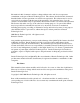
QuickClip ™ Connect the external reference (Genlock) input/loopthrough (this will be one of the connections on your video Capture/Playback Device) to an external reference source. (See diagram below) Note that in the above diagram, the genlock signal is sent to a distribution amp prior to distribution among the video equipment that needs to be genlocked. Also, the cables connecting the distribution amp to the equipment should be matched both in quality and length.
QuickClip ™ Setting Up External Device Control QuickClip Pro uses the (2) RS-232 serial control ports on the motherboard to control external devices. Using hardware adapters, the RS-232 signal is converted to an RS-422 signal. See the below diagram: This provides two control channels, one for CONTROLLER mode (for external pull-ins) and the other for DEVICE mode (playback via external controller device).
QuickClip ™ o o o o o o o o o o o o Connect the B&B Beige Adapter + Null Adapter to the first RS-422 9-pin connector on the motherboard. Connect a Serial control cable between the B&B Beige Adapter + Null Adapter combination, and the 9-pin remote port on the external controller device. Connect the Drastic RS-232 to RS-422 adapter to the second RS-232 9-pin connector on the motherboard. The end of the adapter labeled RS-232 is to be attached to the connection on the motherboard.
QuickClip ™ QUICKCLIP PRO QUICK START: Overview We strongly recommend that the user read through the entire manual to ensure proper installation, configuration and use of QuickClip Pro. However, we recognize that your time is a precious commodity, so this section allows a quick way to get started using QuickClip Pro.
QuickClip ™ Server Mode: In Server mode, the user captures and plays back digital media as “clips”. These clips are captured (digitized) and show up as files in the storage/hard drive. The clips are not associated with a particular location in time code space. In fact all clips begin with the time code of 00:00:00:00. Server mode enables the PlayList features, which allows the user to sequence a series of clips for playback and includes several commands to trigger playback and sequencing.
QuickClip ™ Front panel VTR editing RM-450 or equivalent Axial Editor DNF 2MCE DNF ST-300 DNF Button Box Odetics Roswell (or equiv.) Louth Automation VTR Mode VTR Mode VTR Mode VTR Mode Server Mode Server Mode Server Mode Server Mode o Launch QuickClip Pro. You will see a Clip Bin for each channel in your system and the Clip Control window. o Attach a video monitor to the video output of your system. o Connect the audio output of the system to an audio monitor (if separate).
QuickClip ™ Video Capture in Server Mode: o o o o o o o o o o o Basic setup: properly installed, configured and licensed workstation with keyboard, mouse, VGA and audio/video monitors, and QuickClip Pro opened and running. Check the Server Mode button check box if it is not already selected. Select a Channel. If you have a one channel system, this will be Int. 0. For a system with multiple channels you will need to confirm which channel you want to record upon.
QuickClip ™ Video Capture in VTR Mode: o o o o o o o o o o o o Basic setup as before: properly installed, configured and licensed workstation with keyboard, mouse, VGA and audio/video monitors, and QuickClip Pro opened and running. On the Clip Control interface, check the VTR Mode button check box if it is not already checked. Open the VTR Mode TC Edit List window to view any media you may have recorded into time code space. This is the VTR Mode equivalent of the Clip Bin.
QuickClip ™ Once the recording has stopped, your captured video is now stored on your hard drives and may be accessed for editing/playback purposes. You may also view the material you have recorded in the VTR Mode TC Edit List. External Pull-ins: This will work in either VTR mode or Server mode. In VTR mode your captured media can be accessed using time code, and in Server mode you will be able to access your media as a clip or series of clips.
QuickClip ™ o o o o o o o o o o o o o o o o o Connect an external reference source (Genlock or Blackburst) to the external reference input (X-REF IN) of your system and to the external reference input of the VTR. Please see our Cabling and Genlock section for recommendations. The transport controls on QuickClip Pro should now operate the VTR. Time Code on the Clip Control window should match the VTR’s time code. Select New External Pull-in from the QuickClip Pro main menu, under File.
QuickClip ™ Video Playback: QuickClip Pro allows the user to control the playback of compatible digital media files (video/audio files) utilizing the video capture/output hardware specified in the requirements section. In VTR mode, the user can play digital media as a section of “time code space”. Time Code Space appears as a 24-hour long virtual videotape striped with black. The user may start playback anywhere within the time code space, and end anywhere.
QuickClip ™ Video Playback in Server Mode: o o o o o o o o o o o o Basic setup: properly installed, configured and licensed workstation with keyboard, mouse, VGA and audio/video monitors, and QuickClip Pro opened and running. Check the Server Mode button check box on the Clip Control window. Select the appropriate channel on the Clip Control interface (lower right hand corner) for playback. If there are clips in the Clip Bin, confirm that AutoLoad is checked, and select one clip with your mouse.
QuickClip ™ Video Playback in VTR mode: o o o o o o o Basic setup: properly installed, configured and licensed workstation with keyboard, mouse, VGA and audio/video monitors, and QuickClip Pro opened and running. Check the VTR Mode button check box on the Clip Control window. Press play. Your video will now play from 00:00:00:00 all the way through its 24hour virtual time code space.
QuickClip ™ The QuickClip Pro Tutorial In this section, we take you through a tutorial of the QuickClip Pro Software.
QuickClip ™ Open QuickClip Pro To accomplish this you may double-click on the QuickClip Pro icon on your desktop as above, or… …through the Start menu, in Programs, inside the Drastic Technologies Folder, inside the QuickClip folder, select the QuickClip option. This will open QuickClip Pro software. In the following diagram, the QuickClip Pro graphical user interface is opened, and two windows are open within it: the Clip Control window and the Clip Bin window.
QuickClip ™ The QuickClip Pro Interface In the above diagram, we see the QuickClip Interface. The following windows are opened: The VGA Preview window, the VTR TC Edit list, the Clip Control and the Clip Bins. QuickClip will enable one clip bin for every channel of output available. Clip Bins contain the captured video, and display the media in Server mode. Note that in this example the user sees an internal Clip Bin (Int.0) and the VTR Mode TC Edit List window.
QuickClip ™ Video Capture Server Mode The Clip Control window. To demonstrate capture functions in Server mode, you will record a Clip. o Check the button titled “Server Mode” from the Clip Control window. o Confirm that you have a live video signal (either from tape or camera) connected to the video input of the system. o With the unit in stop and your video source active, you should see pass-through video on this monitor. Pass-through audio should be present as well.
QuickClip ™ o Click on the Record button At the top center of the Clip Control window, select the Record button. Pressing this brings up the New Clip Settings window, as below. o Assign a name At this point, you may assign a name to the clip to be recorded. Note that QuickClip offers a default clip name based on a DRCL prefix and a number. If you select the entire default clip name with your mouse, you can enter a new name for the clip using your keyboard.
QuickClip ™ o Press OK When you press the OK button, recording begins immediately and will record for the duration specified in the Max Length field. If you have not selected the Max Length, QuickClip Pro will begin recording and continue until you press the Stop button (or any other button on the Clip Control interface), or until you use up all the available storage. In the above diagram, QuickClip Pro is in the process of recording your clip, TESTCLIP.
QuickClip ™ Multi Channel Sync Record Sync Record This allows the user to synchronize the “Start Record” of more than one available channel. Selecting the Sync Record button opens the above window: Depending on the hardware/software package you have assembled, you may have multichannel capabilities. If it is necessary for you to record more than one channel at a time, the multi-channel sync record allows you to synchronize the record start of these incoming channels.
QuickClip ™ VTR Mode To demonstrate capture functions in VTR mode, you will record media into time code space. o Check the “VTR Mode” button in the Clip Control window. In VTR mode, QuickClip Pro utilizes time code space to handle media. In time code space, there are no clips. Therefore there are no Clip Bins or PlayLists.
QuickClip ™ o Select a Channel Confirm that QuickClip Pro is set to the Int. 0 channel. The channel dropdown menu is located on the bottom left of the Clip Control interface. o Set the Video Standard. In the Clip Control window, above the transport controls, to the right of the time code numbers are the time code type and the video standard. The video standard may be changed by simply clicking on the type (DF, NDF, etc.) with your mouse. This action cycles through the available time code types.
QuickClip ™ Add Media to Time Code Space To add media to time code space, press the “Add” button. The below screen will appear. The user may then select any recorded file(s), whether recorded in VTR Mode or Server mode. In this way, material gathered as Clips may be inserted into Time Code Space as necessary. Navigate through the internal drive, attached storage or storage on a network to find the media you need to add.
QuickClip ™ This will open the above “Add to TimeCode Space” dialogue box. The clip particulars will be displayed under the Clip Extents section. The user may add either audio or video or both audio and video to this time code space. The above parameters would place the selected media at the in point of 00:00:00:00. Also, as the V1 and V2 buttons are both deselected, the above setting would simply add audio to the time code space selected, whether or not video is present at that location.
QuickClip ™ Clear Media from Time Code Space If you need to clear a section of media from Time Code Space, press the “Blank” button. The above screen will appear and the user will be able to easily clear a section of Time Code Space for recording. If the user has a section of video where the audio needs to be replaced, they may use this screen to remove the audio tracks only. Press the V1 or V2 buttons. These can be selected or deselected based on the needs of the user.
QuickClip ™ Blank Time Code Space If you need to clear all of the media from Time Code Space, press the “Clear” button. The “Blank TimeCode” screen will appear as above. This is the same as the Blank TimeCode detailed in the Blank TimeCode Space section, but with the End TC set at 24 hours minus one frame, the end of time code space. The default setting allows the user to clear all the media from their time code space.
QuickClip ™ External Serial Device Control With QuickClip Pro, you can control the actions of a supported VTR to perform frameaccurate pull-ins of video from an external deck. An external pull-in is basically taking source material from an external VTR according to the time code, allowing for frame-accurate capture of media. This avoids the recording of extraneous media, and saves space on your storage. Note that not all VTRs are capable of frame-accurate responses.
QuickClip ™ Confirm that QuickClip Pro is closed. Open the Local Config section of the software. This should be available in the Start Menu, under Programs, in Drastic Technologies. LocalConfig Menu o Check the Serial Control in the Global Config section o Check the VTR Control in the Global Config section o Set the Edit On to 0. o Set the Edit Off to 0. o The COM ports can be assigned to external device control or serial control, as the user decides.
QuickClip ™ press the “Add” button to add it. Confirm that Ctl1 is selected in the Channel field. o Now touch the pull-down arrow to the right of the “Port” window to select COM 1. This action assigns the COM 1 port to Ctl 1, for QuickClip Pro to respond to external controller devices. o Assign the second available COM port to external serial device control (“External” section in LocalConfig). If Ext0 is not present in the “Channel” field, press the “Add” button to add it.
QuickClip ™ External Pull-Ins The VTR and your system will be set up as above in External Serial Device Control. o Close LocalConfig and open QuickClip Pro. Note that LocalConfig must be closed before you open QuickClip Pro or no settings will be saved. o Select a channel. In this case you will need the external channel. o Set the Video Standard. In the Clip Control window, above the transport controls, to the right of the time code numbers are the time code type and the video standard.
QuickClip ™ o Confirm that the Time Code Type matches the Control Type found on the QuickClip Clip control Menu. This can be found to the right of the time code, in the Time Code window of the External Pull-In Menu. It is the top of the three fields here, represented in the below diagram by the NDF (non-drop frame). o Select the control type CTL, just under the time code type. o Set the “head” (the amount of frames your system will record prior to the In point you have chosen) to 0.
QuickClip ™ record by time code. Find a good In point and press In. Note that the In time code field immediately updates to display your present location. o Shuttle forward and find a good Out point. Set this point by pressing the Out button. o Press the Set Clip button. This will set the information you have entered memory. o Once you are satisfied with the material you have selected, simply press the Single button.
QuickClip ™ Capture via EDL QuickClip Pro allows the user to import media from specific industry standard equipment via an EDL (Edit Decision List). Supported EDLs include: Avid Log CMX 34xx Sony 8/9x00 GVG 1-2.4 GVG 2.4+ DVision Drastic EDL Drastic LOG An EDL is a very simple file type that contains information regarding digital media that can be addressed via time code.
QuickClip ™ o Select the Video Input type Select from the video input type pull-down list on the Clip Control interface. Confirm that this type matches the actual live input you have connected to the unit. If this is not selectable, your hardware may not possess the capability to record this type of video. o Select the Audio Input Type on the Clip Control interface. o Open your EDL Go to the Main Menus, under File, select Open Specific List.
QuickClip ™ Video Playback Server Mode o Check Server Mode This will activate the Clip Bin(s). If you do not see the clip bin you need, you may be able to open it using QuickClip Pro’s main menus, under Channels. o Load the Clip Confirm that the AutoLoad is checked in the Clip Bin. If the clip you have just recorded is not in the Clip Bin, remember to press the “Stop” button on the Clip Control interface.
QuickClip ™ PlayList Features QuickClip Pro allows the user to sequence and schedule the playback of digital media, in Server mode, using PlayLists. PlayLists offer a way to sequence a number of clips and command the sequence to play. Clips may be easily edited and placed into a PlayList. There are a few ways to create a new PlayList. You may click on the Create New PlayList button on the toolbar or select New, located under File on the main menu. Choose the option New PlayList.
QuickClip ™ You could put the rest of the Clips into the PlayList using the drag and drop method. o Copy and Paste using Right Click Menu Commands Go back to the Clip Bin window and click on the TEST2 clip. Right-click on it to bring up a Clip Editing options menu. Select Copy. Click on the PlayList so that it is activated and then rightclick on the TEST1 clip in the PlayList, and select Paste Below. The same TEST2 clip will be added to the bottom of the list.
QuickClip ™ o Wait Command There may be situations where your playback application requires that the unit either start playing at a certain time, or pause until a clock-defined time and resume playing a PlayList. You could choose a Wait command from the Insert Command option in the PlayList. Set the time of day you wish the list to start or resume playing.
QuickClip ™ o Save the PlayList Confirm that the PlayList is the active window. Press the button labeled Save As on the toolbar to save the PlayList. The above window will appear. You will be prompted to rename and save the PlayList. Note that the title bar of the PlayList window now shows the name of the PlayList. You could have several versions based on the same PlayList and call them up as needed.
QuickClip ™ Press the Play Break button and our list will play. Press the Abort button to stop playback, if desired. o Create a version of a Clip for the PlayList Editing a Clip in the PlayList only affects this one instance of the Clip, so that each PlayList could have slightly different versions of the Clip in them without duplicating media. o o o o o o o Double-click on any one of the clips in the PlayList. This sets the focus to the Clip Control window and loads the clip into it.
QuickClip ™ Instant Replay T-Bar Shuttle The T-Bar Shuttle allows the user to view a user-selectable portion of a clip while it is being recorded for Instant Replay applications. (Read while Record capability) Not available on all models. The top number (in this case a 200) displays the maximum speed available for playback. This value is user-editable. The box just below that is the current playback speed.
QuickClip ™ VTR Mode In VTR mode, QuickClip utilizes time code space to handle media. The time code space is equivalent to standard VTR tape which has been pre-blacked starting at 00:00:00:00 and ends at 23:59:59:29. Media may be inserted anywhere within this tape and intermediate frames will be displayed as black with silence. Here is the QuickClip Clip Bin. Note that in VTR Mode the clip bin is disabled. VTR Mode uses Time Code Space to define the virtual location of the media.
QuickClip ™ o Check VTR Mode This will deactivate the Clip Bins, and deactivate the Clip Pulldown menu (to the right of the Next button). The browse button is also not selectable. o Press Play Pressing Play at this point will allow the user to play the entire time code space from their present location to the end. To reach a particular location, simply enter the time code into the In point on the Clip Control interface and press Q.
QuickClip ™ Editing Clips o Check Server Mode edit a clip. This will activate the Clip Bin(s) and allow the user to o Open the Clip Edit Window To edit your clip, double-click the TESTCLIP Clip in the Clip Bin window. This will open the Clip Edit window and load your clip for editing. The Clip Edit window’s purpose is to create modified versions of Clips in the Clip Bin(s).
QuickClip ™ Edit a Clip using the In and Out buttons o Q back to the In Point To create our new clip, press the Q beside the In time code edit box (this cues to the first frame of the clip if you have moved from the beginning) and then press Play to move through the video. Press Pause to stop playback at about 5 seconds in. o Select an In Point Press the In button and the time code of our present location will become the new In point. The “In” time code box will change to reflect the new In point.
QuickClip ™ Editing a Clip with Time Code o Enter an In and Out point With your mouse, highlight the entire current time code in the edit box showing the In point and enter a time of 00:00:25:00. Note that you may simply enter the number without the colons. Press the Set In point button to set this as your new In point. Press Tab until your focus is on the Out edit box where you can enter a new time of 00:00:55:00. Select the Set Out point button.
QuickClip ™ o Enter a New In Point Select the time code In Point with your mouse. Enter a new In Point using your keyboard. Note that all “clips” begin at 00:00:00:00, and you will have to enter a legal time code location. Thus, your clip In point cannot be before the beginning, or after the present end of the clip. Once you have input a new legal time code location into the In Point box, press the In button. o Enter a New Out Point Select the time code Out Point with your mouse.
QuickClip ™ Video Standard QuickClip Pro handles NTSC, PAL, Film (24fps) Rate and HDTV video standards, depending on the version and hardware configuration. Time Code Source QuickClip Pro allows the user to control their system using different time code source types. These are selectable through the QuickClip Pro interface. If VITC (Vertical Interval Time Code) is selected, QuickClip Pro will use the VBI (Vertical Blanking Interval) to receive time code control.
QuickClip ™ Product Overview QuickClip is a series of software-only digital disk recorder solutions. These products provide VTR functionality, with nonlinear access and expanded operational modes for the traditional video editing, animation, insertion and display environments. QuickClip is offered in the following versions: QuickClip Pro – A software-only VTR/DDR emulator and VTR controller. Supports a subset of the VVW functionality for single channel use. See Supported Hardware below.
QuickClip ™ QuickClip Pro Reference Guide Clip Control Window Clip Control Interface This tutorial will examine the following portions of the Clip Control window separately: The Transport Control, the Clip Management, the Time Code Edit, and the Video Setup sections.
QuickClip ™ The Transport Control Section Time Code window The Time Code is displayed in (00:00:00:00) format (HOURS:MINUTES:SECONDS:FRAMES), or (HH:MM:SS:FF). Transport Status window This will display whatever action is taking place within the transport control section. In this case, we see the pause button pressed, and the Transport Status window shows “Pause". Fast Rewind button This will zoom backward while playing at the greatest speed (-1200%) until it reaches 00:00:00:00.
QuickClip ™ Five Seconds Rewind button This will move to a time code location five seconds before the present location, pause and display the frame of video located there. If located at a point less than 00:00:05:00, it will go to 00:00:00:00 and pause on that frame. Reverse Play button This will “play” the video in reverse (-100%) until it reaches 00:00:00:00. It will then pause on that frame. Pause button This will stop transport at the current location, and pause on that frame.
QuickClip ™ The Time Code Edit Section Record button Pressing this button in Server mode will bring up the new clip settings window, and allow the user to set up the recording of a clip. In VTR mode, this will put the system into crash record mode (start recording at the present location, no out point specified). Eject button In an external control situation, this will cause the external VTR to eject its tape.
QuickClip ™ In Time Code window The time code for the first frame of video in the selected clip will be displayed here. By clicking within this window with the mouse, the time code found here can be edited by keyboard. Note that the In time code must be “Set” after being entered. Out Time Code window The time code for the out point of the edit will be displayed here. By clicking within this window with the mouse, the time code found here can be edited by keyboard.
QuickClip ™ The Video Setup Section Note that not all system hardware supports access of these controls through the QuickClip Pro interface. If as in the below diagram there are no slider bars on the controls in your version, then the controls are not enabled. Video Channel(s) There will be a selectable/de-selectable button for each channel of video input. In VTR mode the user may de-select the video channel for example if an audio-only recording is required.
QuickClip ™ Chroma Level This slider adjusts the chroma (saturation) level for the selected channel. The Saturation setting acts like a TBC chroma setting for the composite and Y/C inputs only. This setting adjusts the current input only. The video input settings for Composite and Y/C are maintained separately. This setting may be accessed through the QuickClip Pro Software, in the Video In tab of the Options Menus.
QuickClip ™ The Clip Management Section Shuttle Bar This bar will display your current location within the selected clip, the blue area being representative of the entire clip and the little gray bar, your location. Also, while QuickClip Pro is playing a clip, the location of the little gray bar will indicate play speed. You can shuttle through the clip by “grabbing” the bar with your mouse and moving it. Next Clip button Go to the next clip in the PlayList.
QuickClip ™ VTR Mode checkbox Use transport controls in traditional VTR mode, time code space only, no Clips or PlayLists in this mode. Assemble and Insert Edit capability. Server Mode checkbox Use the transport controls in Server mode, clip-based media control. PlayLists can be assembled, offering sequenced playback of media with added command features. Video Type window Choose your video input type in this box. The pull-down list will display a list of video input type choices available to your system.
QuickClip ™ Main Menus The main menus allow for Windows-based control of the various parameters needed to operate QuickClip Pro. Select the File menu. File Open Clip Bin New Creates a new PlayList or External Pull In Add Media Files Browse through your storage for your media. Open List Opens a specific PlayList or External Pull In Close Closes the current list License license.
QuickClip ™ Save As Saves a PlayList, External Pull In, Clip Bin, TC Space, EDL or Inverted EDL with a new name entered by the user Exit Exits QuickClip Edit – PlayList Mode Edit a PlayList or Clip. Note: You must have either the PlayList window or the Clip Bin window selected for this menu to be enabled. Also, choose Server mode, as VTR mode does not support Clips or PlayLists. PlayList Mode Cut Removes the selected clip and maintains it in the buffer until it is replaced by another cut or copy command.
QuickClip ™ Remove Removes the selected clip from the PlayList but maintains the original clip in the Clip Bin. Insert Command Opens the Command Edit window, allowing the user to insert a command into a PlayList.
QuickClip ™ View The View Menu Toolbar Toggle the display of the QuickClip toolbar on or off. Status Bar Toggle the display of the Status Bar on and off.
QuickClip ™ The Clip Control Window – Small Size Options The Options menus are opened through this item. Before recording any clips it is always better to check all the settings in the option. It can be seen under View. Most of these settings are automatically set when you select a specific model on the local configuration. But it is better to check everything over again.
QuickClip ™ Audio In All channels must have the same input All audio sliders are set to high but can be set to users’ needs. Audio Out All channels must have the same output All audio sliders are set to high but can be set to users’ needs. Storage Select a directory to record into. It may be useful for you to create folders within this directory which help you to identify the media files you are creating.
QuickClip ™ Options Menus Local System The Options Window – Local System Menu Driver Configuration Direct Hardware Enable hardware-specific uncompressed standard definition and uncompressed high definition capabilities. This will be checked to enable appropriate hardware when it is applicable to your unit. Do not adjust this setting except where instructed to by QuickClip Technical Support. Direct Show Enables hardware-specific Direct Show protocol.
QuickClip ™ QuickTime Enables QuickTime applications. This will be checked to enable appropriate hardware when it is applicable to your unit. Do not adjust this setting except where instructed to by QuickClip Technical Support. DDR DLL (Digital Disk Recorder Dynamically Linked Library) Used for external control. This will be checked to enable appropriate hardware when it is applicable to your unit. Do not adjust this setting except where instructed to by QuickClip Technical Support.
QuickClip ™ Media Reactor Version Hardwarespecific information displayed here. File Conversion utility. Not present on all systems. Local Setup Channel Enabled This will be checked to enable appropriate hardware when it is applicable to your unit. Do not adjust this setting except where instructed to by QuickClip Technical Support. (model-specific) Configure Channel This will be checked to enable appropriate hardware when it is applicable to your unit.
QuickClip ™ General The Options Window – General Signal Format Pull-down menu of applicable formats. Some versions can capture or play back more than one signal type. Use this menu to select between types. Internal Format (Compression) Type The compression type will be displayed here. Some systems feature user-adjustable compression. If your system supports more than one compression type, use the pull-down menu to select the appropriate one. Note that some systems use uncompressed video.
QuickClip ™ Rate The Compression Rate, Data Rate, and Compression Ratio will be displayed here. The user may be able to adjust these rates (model-specific). GOP Structure Pull-down menu offers Group of Picture choices that will result in legal MPEG-2 file types. (model-specific) GOP Size Size of Group of Pictures (in frames).
QuickClip ™ Misc (Def Still Length) time (in frames) that the still images will be displayed Define the length of Inhibit Recording Check to inhibit recording. (model- Inhibit Deletion Check to inhibit deletion. (model- specific) specific) Status Storage Available Total storage available to the system expressed in Megabytes Time @ Current Rate Total amount of video storage available, calculated at the current rate expressed in “00:00:00:00”, or “hours:minutes:seconds:frames” format.
QuickClip ™ Video In The Options Window – Video In Video Input Pull-down menu of applicable formats for Video Input: e.g. Composite, S-Video (Y/C) or Component. Broadcast (on/off) Checked to enable specific hardware when it is applicable to your system. Do not adjust this setting unless instructed to do so by QuickClip Technical Support. Input TBC (Time Base Corrector) Note that there is a “D” below each slider, which stands for the word “default”.
QuickClip ™ Return to Default The “D” at the bottom of the slider stands for default, which you can return to by pressing the “D”. The default level for Setup is 50. The video input settings for Composite, Y/C and YUV are maintained separately. Video Video (Contrast) adjusts the luminance range for the current input only. It is disabled if the Automatic Gain Control is enabled. The default level for Video is 50. The Video settings for Composite, Y/C and YUV are maintained separately.
QuickClip ™ Automatic Gain Control (off/on check box) This setting may adjusted separately for each input, as opposed to the general TBC settings above. Automatic Gain Control attempts to compensate for video inputs using the Brightness (~Setup) and Contrast (~Video) settings below. If the AGC is enabled, then the settings below will not be active. For fine-tuning of the Y/C or YUV signals, this should be disabled, but should normally be enabled for Composite.
QuickClip ™ Video Out The Options Window – Video Out Video Output Select the Video Output to which the changes you have entered will apply. Filter Select or de-select the filter through this pull- down menu Output TBC (Output Time Base Corrector section) Setup Setup (Brightness) adjusts the intensity of the video level for the current input only. It is disabled if the Automatic Gain Control is enabled. The default level for Setup is 50.
QuickClip ™ Video Video (Contrast) adjusts the luminance range for the current input only. It is disabled if the Automatic Gain Control is enabled. The default level for Video is 50. The Video settings for Composite, Y/C and YUV are maintained separately. Hue This setting adjusts the Hue (the wavelength) of the current input channel. The default level for Hue is 0.
QuickClip ™ Lock Genlock, or timing synchronization selection. The choices here are Ref In, None or Current Output. With None selected, the user will not be able to ensure frame accurate media handling in external pull-ins. Horizontal Phase Horizontal synchronization information. This setting is adjusted using a slider, which displays the results of your manipulation as a number from 0 to 65536. Sub Carrier Chrominance synchronization information.
QuickClip ™ Audio In The Options Window – Audio In Audio Input Pull-down menu of audio types associated with your system. Audio Inputs Input Level for up to 8 channels. These settings are adjusted through the use of sliders, which display the results of your manipulation as a number from 0 to 100. The “D” at the bottom of the sliders stands for default, which you can return to by pressing the “D”. LTC (Longitudinal Time Code) (model-specific) Enable Enable the LTC.
QuickClip ™ Enable Enable the DTMF. Match Output Used for synchronizing the DTMF output Listen Model-specific audio monitor setup Advanced Opens Audio Input advanced settings. Audio tracks 5 – 8 are not displayed and pull-down menus specific to the audio input settings are offered. Below is the Audio In menu with “Advanced” selected. Note that the “advanced” button has become the “basic” button, which allows the user to return to the basic “Audio In” menu.
QuickClip ™ Original Flag MPEG-2-specific audio file setting. Error Protect Flag MPEG-2-specific audio file setting. Copyright Flag MPEG-2-specific audio file setting. (hardware-specific) (hardware-specific) (hardware-specific) Audio Slave Basic MPEG-2-specific audio file setting. (hardware-specific) Use this button to return to the basic audio settings menu. Channel Selector Select the channel to which your changes will apply. Done Use this command to exit the options menu.
QuickClip ™ Audio Out Audio Output Options menu Audio Output Drop-down menu of available audio output types. Model-specific. Audio Outputs Level for up to 8 channels These settings are adjusted through the use of sliders, which display the results of your manipulation as a number from 0 to 100. The “D” at the bottom of the sliders stands for default, which you can return to by pressing the “D”. LTC (Longitudinal Time Code) (Model-specific) Enable Turn the LTC on or off.
QuickClip ™ DTMF (Dual Tone Multi Frequency time code) (Model-specific) Enable Turn the DTMF on or off Match Input Used for synchronizing the DTMF output Channel Selector Select the channel to which your changes will apply. Done Use this command to exit the options menu.
QuickClip ™ Storage The Options Window – Storage Playback Ignore AVI/ODML This will be checked to enable appropriate hardware when it is applicable to your unit. Do not adjust this setting except where instructed to by QuickClip Technical Support. Not supported on all versions. Ignore QuickTime This will be checked to enable appropriate hardware when it is applicable to your unit. Do not adjust this setting except where instructed to by QuickClip Technical Support. Not supported on all versions.
QuickClip ™ Ignore Stills This will be checked to enable appropriate hardware when it is applicable to your unit. Do not adjust this setting except where instructed to by QuickClip Technical Support. Not supported on all versions. Recording File Type This will be checked to enable appropriate hardware when it is applicable to your unit. Do not adjust this setting except where instructed to by QuickClip Technical Support. Not supported on all versions.
QuickClip ™ this setting except where instructed to by QuickClip Technical Support. Not supported on all versions. Audio File Type This will be checked to enable appropriate hardware when it is applicable to your unit. Do not adjust this setting except where instructed to by QuickClip Technical Support. Not supported on all versions. Refresh Refresh the information on the screen. If you have made a change and do not see it, press this button to update the image on your screen.
QuickClip ™ Channels The Channels menu displays and selects the available channels. Internal All internal channels will be listed here. If the Clip Bins you are working on are closed and need to be re-opened, you can re-open them by selecting them through this menu. You can also shift the focus or selection of a Clip Bin by choosing them through this menu. External Open an external channel or channels. Not supported in all models. Network Direct access to a network. Not supported in all models.
QuickClip ™ Window New This command opens up a new PlayList. Close This command closes the currently selected window. Close All This command closes all open windows. Note that this includes the Clip Control window and the clip bins. Check out the list at the bottom of the Windows menu, which shows all active windows in the QuickClip screen. The Clip Bins will not be on this list if they are closed. Open QuickClip windows may also be closed by pressing the X in their upper right corner.
QuickClip ™ Arrange Icons Direct the arrangement of your desktop icons. Not supported in all models. Clip Control The Clip Control window may be opened here. If it is already opened, this command will select the Clip Control window. If the Clip Control window is opened, it will be displayed in the list at the bottom. Clip Edit The Clip Edit window may be opened here. If it is already opened, this command will select the Clip Edit window.
QuickClip ™ Multi Channel Sync Record Note that in this instance there are four channels listed, and three are enabled. This corresponds to an application wherein a unit with three inputs synchronizes all three inputs (cameras in this case) to start recording at the same time. The "Lock Names" selector box attaches the same prefix to all three recorded clips, adding (in this case a 1, 2 and 3) to the end so as to identify the channel the clip was recorded on.
QuickClip ™ T-Bar Shuttle T-Bar Shuttle The T-Bar Shuttle allows the user to view a clip while it is being recorded. Note that audio is not available until the user has stopped the recording of a clip. T-Bar features are not available on all QuickClip Pro versions. Following are the descriptions for the buttons and fields in the TBar Shuttle section of the QuickClip Pro interface. Maximum Playback Speed This is the maximum play speed allowed in the forward play section.
QuickClip ™ playback will occur. Note that entering a negative number in this field will cause reverse playback. Current Playback Speed The second window from the top lists the current playback speed as a percentage of standard (100%) playback speed. 0 indicates that the unit is not in Play mode. Play Shuttle at normal play speed. Pause Stop Playback and display the frame of video at the current location. Reverse Play Shuttle in reverse at normal play speed.
QuickClip ™ Maximum Reverse Speed This value defines the maximum shuttle bar speed in reverse. If the user “grabs” the Shuttle Bar with their mouse and pulls it all the way to the bottom, playback will occur at the maximum speed entered here. In this case the user has entered -100%. This setting plays video at 100% (the same as forward play), but plays it in reverse. If the user were to enter -200 in this field, playback would be 2X in reverse.
QuickClip ™ Help The Help menu produces the user the “About” screen, which calls up a screen offering the QuickClip software version number and some contact information for Drastic Technologies Ltd. The Help Topics menu item (grayed out) is reserved for future development considerations. The Help files regarding the QuickClip Software are limited to bubble help windows that open if you hover above an icon for long enough.
QuickClip ™ The Toolbar New PL Creates a new PlayList New PI Creates a new Pull In Open Opens a saved PlayList Save Saves the selected PlayList Save As Saves the selected PlayList with a new name Save All PlayLists Close List Saves all windows in the workspace, including any open Closes the selected list Cut Removes the current clip and maintains it in the buffer until it is replaced by another cut or copy command.
QuickClip ™ Paste At End Pastes the clip from the buffer at the end of the PlayList Delete Deletes the selected clip 107
QuickClip ™ The PlayList Status Bar The Status Bar displays the status of clips within a Break and the percentage of the current Break played. Select Break Selects all the clips in the Break, starting from the selected clip to the end of the PlayList. Upon pressing play, the PlayList will begin playing. It will play from the first selected clip to the end of the PlayList, unless instructed otherwise by a command or commands. Break Display (top window) and Clip Run (bottom window).
QuickClip ™ Add Clip Add the next clip in the list (Clip Bin) to the break. Abort Abort playback of the Break. Puts QuickClip Pro into Stop mode. Channel Select The Channel Select drop down box displays the currently selected output channel. The user may change the channel assignation using this pull-down menu. Play Clip Plays the selected clip Pause Clip Pauses playback of current clip Stop Clip Stops playback and puts the system into pass-through mode.
QuickClip ™ Clip Out The clip Out point (or the Command details) Break In Time Code of In point of clip (or blank if command line) Break Run The Break Run displays a total run time for the Break Comment Clip comments or Command description.
QuickClip ™ Edit Clip Calls up the clip edit window, allowing the user to edit a clip in the PlayList. Note that editing this clip will not affect the original clip as it was captured, only this instance of the clip. Preview Clip Play the selected clip on the selected output devices. Preview Group Preview a group of clips, as selected. Note that this is only active when more than one clip has been selected by the user.
QuickClip ™ The Command Edit Window The Command Edit window Available Commands: BREAK – Start on any keypress Wait for an external controller command or keypress on the keyboard or front panel controller. Note that the Space bar, the Enter key and the Tab key (as well as other non-alphanumeric keys) are not considered a keypress for the purposes of the Start on any keypress command.
QuickClip ™ Command option from the menu. Select the command that you require. QuickClip Pro will insert the command below the item you have right-clicked on. When you are done, press the SET button on the Command Edit window. This will put the changes into the list. Note: If you don’t press the SET button, the Command Edit window will as a default select the most recently used type of command to place into your PlayList.
QuickClip ™ The Status Bar The Status Bar The status bar will show the current Synchronization timer and date, which will be used as the current internal timing source. To the left of the date is the GPI trigger status. This is available only if a GPI trigger is enabled. It will display the status of the GPI triggers and the may be set by pressing the button with the mouse on each trigger status. The status bar may be disabled via the View and Status bar option.
QuickClip ™ Local Config Below is the Local Configuration menu. This is where the user may adjust a number of settings for QuickClip Pro. Below is the Local Configuration menu separated into the following subsections: Global Config, External, Control, Internal and Record To. We will further examine the properties represented in each of the sections of this diagram.
QuickClip ™ LocalConfig - Main Menus This is the File pull-down menu. Under the file menu, the user may set the base configuration simply by selecting the appropriate model as instructed by a QuickClip support technician. When the user selects a new configuration, the following confirmation screen will come up: The user must agree to reset at this time, or cancel out of the action.
QuickClip ™ This is the About pull-down menu. Select About Local Config to view the version number of LocalConfig. If you need to contact QuickClip Technical Support regarding your software, take note of any version information. We may be able to use this information to effect a speedy resolution of your situation.
QuickClip ™ Global Config These settings enable specific hardware when it is applicable to your unit. Do not adjust these settings except where instructed to by QuickClip Technical Support. Not all settings supported in all versions, as many of these settings are specific to the hardware upon which QuickClip Pro is installed. Direct Hardware Enables Direct Hardware protocol for specific hardware. Note that if Direct Hardware is checked, Direct Show should be unchecked. Not supported on all versions.
QuickClip ™ External Control of an external VTR may be assigned a port through this portion of the Local Config window. You may add or delete a channel of external control, and switch port assignations through this channel. If you need to change any of these assignations, it will be either because you know what you are doing, or you have been instructed to do so by QuickClip Technical Support.
QuickClip ™ (Baud Rate) The Baud Rate will be displayed here. The default is 38.4k 8-o-1. Video Standard Select from a pull-down menu of available video standard choices in this menu. (i.e. NTSC, PAL etc.) Edit On Set the length of the pre-roll for an edit to be performed on. The pre-roll value is expressed as a number of frames. This setting may be adjusted as necessary for the particular device you are controlling. Off Set the length of the post-roll after an edit.
QuickClip ™ Control Determine where the channel or channels of Control Input will be assigned. This refers to control of the system by an external device. Channel The drop down menu for the channel shows all Control In channels that have been enabled. In a two channel box, there will be two channels of for control of your system by an external source. The standard arrangement for these has the first channel identified as Ctl0, and the second channel is Ctl1. Add Add a channel of Control In.
QuickClip ™ Type This drop down menu for industry standard supported control protocol types offers the user a quick method of confirming the protocol types used by QuickClip Pro. Consult with QuickClip Technical Support if the device type you need to emulate does not appear. Sony 422 Enable the use of Sony protocols. The default setting is Odetics Enable the use of Odetics protocols. The default setting “selected”. is “selected”. Louth Enable the use of Louth protocols.
QuickClip ™ Edit On This represents an adjustment (in frames) that QuickClip Pro will wait after receiving the Edit command. This setting is used to synchronize external control. Off Frames after the Edit off command is received. This setting is used to synchronize external control. Phase The Phase may be adjusted (in milliseconds) by entering a number value in this field. Do not adjust this setting unless directed to do so by QuickClip Technical Support. Offset The Offset default is 0 ms (milliseconds).
QuickClip ™ Internal This section determines the presets for each internal channel supported by your system. If you need to change any of these assignations, it will be either because you know what you are doing, or you have been instructed to do so by QuickClip Technical Support. Do not experiment with the default settings, as this may result in a loss of communications within the board set, undermining the functionality of the unit. Channel In a single channel box, the internal channel will be Int0.
QuickClip ™ Add Add an internal channel of video. Note that this must be supported by the hardware. The External, Control and Internal channels are all routed through the same system, and must be assigned logical pathways through it. Del Delete an internal channel of video. (Are you sure you want to do this?) Note that channel “Int0” may not be deleted. Edit On This represents an adjustment in milliseconds that QuickClip will wait after receiving the Edit command.
QuickClip ™ Force VGA This checkbox opens the VGA display, which will support a preview quality display window appearing on your VGA monitor in addition to the QuickClip Pro interface, for use during clip manipulation and editing. For more information, consult QuickClip Technical Support. Enable Enable the choices selected in the Channel window. The default setting is for this box to be checked. Confirm that what you select is supported by the hardware in your system.
QuickClip ™ Main Directory of Clip and Time Code Folders. This window displays the directory within which the New Clip and the New Time Code Space Files will be located. If you have determined that you need to change this directory, it should be because you know what you are doing or because you have been directed to do so by a Drastic technician. Selecting the browse button at the right of this pull-down menu brings up the below standard Windows browser, so you can find the directory you need.
QuickClip ™ Slow-Mo Type Select between available slow motion types using this pull-down menu (model-specific). Replay Select Select between local or network replay, or select disabled to disable network or local replay capabilities. Offset Specify the number of frames for the offset that QuickClip Pro will use in an instant replay application. Compression Type Select between available compression types (or uncompressed depending on your model) using this pulldown menu.
QuickClip ™ Troubleshooting No Video Output Connect a monitor directly to the composite out of the Server. Try loading and playing a number of different clips. Use the monitor to trace the video connection through the setup. No Audio Output Connect an audio monitor directly to the audio outputs of the Server. Make sure the audio levels are all the way up (100%). Try a number of different clips. Use the monitor to trace the audio connections through the setup.
QuickClip ™ generally recognized then newer ones. Make sure the model name is NOT followed by a ‘P’, when running in NTSC. This indicates the PAL version of a VTR. If problems persist, try using a model that the controller is unlikely to recognize. Some controllers’ default behavior is much better than their ‘tuned’ behavior. Enabling/Disabling Serial Protocols Sony 422 – Tape Emulation (VTR Mode) This is the protocol in use by standard videotape recorders (e.g.
QuickClip ™ told it is a VTR. This should allow the ingesting of clips from their time codes. Once that is working, you may want to try and set up the Server as a Clip/Spot based server. It should be noted that the Server is not intended as an ‘on-air’ device. Many automation systems designed with servers are ‘on-air’ only. Normally, the automation system also expects to be able to record or transfer spots onto the device, which is not possible locally with the server.
QuickClip ™ Manufacturer’s Warranty LIMITED WARRANTY (5-a) Terms and Coverage: Drastic Technologies (the Manufacturer) warrants the software product to the original purchaser for a period of thirty days. The warranty period commences on the date of shipment of product by Drastic to the purchaser however the warranty period set forth in the warranty may be extended at the discretion of Drastic by up to 60 days to cover shelf life and transportation to the purchaser’s end-user customer.
QuickClip ™ (2) Buyer shall reimburse Seller for its expense in testing and examining the Goods or replacement parts calculated at Seller’s then current rates. (c) Seller’s liability under this warranty is expressly conditioned upon Buyer’s notification of Seller on any claim by Buyer under this warranty within thirty (30) days following Buyer’s discovery of facts indicating to Buyer that Goods or replacement parts shipped hereunder constitute a breach of this warranty.
QuickClip ™ (c) EXCEPT AS PROVIDED EXPRESSLY ABOVE, SELLER SHALL NOT BE LIABLE TO BUYER, TO BUYER’S CUSTOMERS OR TO ANY OTHER PERSON.
QuickClip ™ QuickClip Technical Support Drastic Technologies Ltd. 12 Drummond St. Suite 3 Toronto, Ontario M8V 1Y8, CANADA Phone: (416) 255-5636 Fax: (416) 255-8780 Tech Support Pager: (416) 406 9829 Toll Free: (800) 830 5184 E-Mail: techsupport@drastictech.com WEB: www.drastictech.