Total solder points: 38 Difficulty level: beginner 1 2 3 4 5 advanced ELECTRONIC TRANSISTOR IGNITION FOR CARS K2543 and starting r e tt e b a g.
Features & Specifications Even the most sceptical one has tot admit that the electronic ignition system has a great advantage over the conventional ignition system. Car constructors now mount such a new system on their most expensive models. THE ADVANTAGES ARE : Better ignition Less air pollution Gasoline economy Better running engine, especially at very high and very low speed Visible less wear of the breaking points, which means a constant calibrated state.
Assembly hints 1. Assembly (Skipping this can lead to troubles ! ) Ok, so we have your attention. These hints will help you to make this project successful. Read them carefully. 1.1 Make sure you have the right tools: A good quality soldering iron (25-40W) with a small tip. Wipe it often on a wet sponge or cloth, to keep it clean; then apply solder to the tip, to give it a wet look. This is called ‘thinning’ and will protect the tip, and enables you to make good connections.
Assembly hints 1.
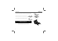
Construction 4. Electrolytic Capacitor. 1. Resistors R... C1 : 0,22µF/630VDC C R1 R2 R3 R4 R5 R6 R7 : : : : : : : 330 330 150 100 150 150 150 5. Transistor T1 (3 - 3 - 1 - B) (3 - 3 - 1 - B) (1 - 5 - 1 - B) (1 - 0 - 1 - B) (1 - 5 - 1 - B) (1 - 5 - 1 - B) (1 - 5 - 1 - B) (1W) (1W) T1 : 2N2219A 1 6. Transistor T2 + heatsink 20mm M3 bolt (1W) (1W) (1W) Insulated washer Heatsink 2. Diodes.
Installing in the car 7. Installing in the car First of all, control the breaker points for a correct setting as per the constructors instructions, or better, use a new set of points, before installing the ignition system. The existing ignition condenser is to be disconnected. This is very important. This condenser may be inside or outside the distributor. ex.: On a 2 cylinders Citroën, this condenser is fitted to the breakers, thus unscrew the nut and remove out of the car.
Installing in the car There are different possibilities to dodge this problem : (1) Install your system under the dashboard (2) Spray a non-conductive protective varnisch (available in every retail shop) on the whole system, of which a "Thick" layer must be applied on the components and the circuit side. Once this layer is dried, a second layer may be sprayed. The ignition system may be fixed under the engine canopy. (3) Build the system into a box well closed, but the heatsink has to be well ventilated.
Test & maintenance 8. Test The installation is now finished. Verify as follows : The condenser is disconnected (very important) All connections are well fixed No lead is misconnected or mixed with another. Now the engine may Start. 9. Maintenance The ignition system on itself does not require a maintenance. The ignition system maintains the breaker points in a good condition, so they will not be burned, as the bring only a few amount of current to the electric system.
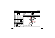
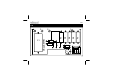
PCB PCB R1 R2 R5 R6 R7 ZD1 ZD2 D3 D4 T1 D2 D1 R3 T2 R4 C1 1 2 VELLEMAN 3 4 9
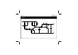
Diagram DIAGRAM 1 R1 R2 330/1W 330/1W R5 150 1W R6 150 1W R7 150 1W 2 R3 150 D1 ZD1 3 150V 150V D3 D2 1N4007 1N4007 T1 R4 100 2N2219A ZD2 1N4007 D4 1N4007 T2 TIP162 C1 .
VELLEMAN NV Legen Heirweg 33, B-9890 GAVERE Belgium (Europe) Modifications and typographical errors reserved © Velleman nv. H2543IP - 2014 - ED1 (rev.