
Assembly instructions Owner manual
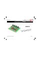

6
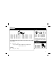
Construction
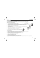
You can also use terminal con-
nectors.
VAC : 2X
OUT1 : 2X
OUT2 : 2X
OUT3 : 2X
OUT4 : 2X
9VDC : 2X
IN1 : 2X
IN2 : 2X
IN3 : 2X
IN4 : 2X
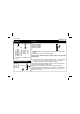
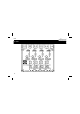
4. PCB tabs
LD1
LD2
LD3
LD4
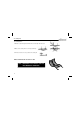
5. LED. Watch the polarity!
LD1
CATHODE
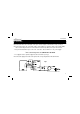
TRI1 : TIC206M
TRI2 : TIC206M
TRI3: TIC206M
TRI4 : TIC206M
Remarks : Make sure the metal backside of the triacs points to the
outputs.
Apply a layer of tin on the entire PCB track.
If you want to switch more than 1,5A per output, then the triacs
need cooling.
You therefore have to mount heatsinks to the triacs. If you mount all
the triacs on the same heatsink, then you have to isolate the
triacs with mica plates and special plastic washers.
The PCB tacks interconnecting the output connectors and the triacs
are not protected by the red solder mask.
We advise you to strengthen these in soldering a copper wire of
1,5mm2 along the whole print. We must take into account that the
entire load current goes through these connections; so up to 4A, if
the triacs are cooled !
6. Triacs
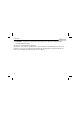
TR...
5mm Red