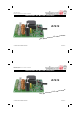
Total solder points: 95 Difficulty level: beginner 1 2 3 4 5 advanced UNIVERSAL AC MOTOR CONTROL K2636 rs. tor moto c e ll o c l of AC d contro e e p s y Eas ILLUSTRATED ASSEMBLY MANUAL Total solder points: 95 Difficulty level: beginner 1 2 3 4 5 H2636IP-1 advanced UNIVERSAL AC MOTOR CONTROL K2636 rs.
Features & Specifications This kit is especially designed to control the speed of drills or any other AC-motors with carbon brushes. Contrary to the usual dimmers, there isn't a phase cut every 1/2 period but only once per period. The moment of cutting determines the speed which can be adjusted from 5 to about 95 %. Owing to this kind of controling, we keep a higher torque at low speed.This does not mean on the other hand, that this circuit cannot be used for a resistive load (e.g. lamps, heating devices.).
Assembly hints 1. Assembly (Skipping this can lead to troubles ! ) Ok, so we have your attention. These hints will help you to make this project successful. Read them carefully. 1.1 Make sure you have the right tools: • A good quality soldering iron (25-40W) with a small tip. • Wipe it often on a wet sponge or cloth, to keep it clean; then apply solder to the tip, to give it a wet look. This is called ‘thinning’ and will protect the tip, and enables you to make good connections.
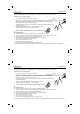
Assembly hints 1.3 Soldering Hints : 1- Mount the component against the PCB surface and carefully solder the leads 2- Make sure the solder joints are cone-shaped and shiny 3- Trim excess leads as close as possible to the solder joint REMOVE THEM FROM THE TAPE ONE AT A TIME ! AXIAL COMPONENTS ARE TAPED IN THE CORRECT MOUNTING SEQUENCE ! You will find the colour code for the resistances and the LEDs on our website: http://www.velleman.be/common/service.aspx 4 Assembly hints 1.
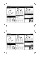
Construction 1. Jumper SK4 3. Resistors Mount jumper according to the main voltage : : : : : : : : 1N4007 1N4007 1N4148 1N4148 1N4148 1N4148 1N4007 : : : : : : 4K7 3K3 680 22K 22K 1K5 (4 - 7 - 2 - B) (3 - 3 - 2 - B) (6 - 8 - 1 - B) (2 - 2 - 3 - B) (2 - 2 - 3 - B) (1 - 5 - 2 - B) Choose operating frequency : 2. Diodes. Watch the polarity ! D1 D2 D3 D4 D5 D6 D7 R... R... R1 R2 R3 R4 R5 R6 J1 : 115V J2 : 230V 4.
Construction 7. Transistors. T1 T2 T3 T4 : : : : 10. Terminal blocks. BC547B BC547B BC547B BC517 13. LED VAC : 2p LOAD : 2p MAINS : 2p LD1 : 3mm RED LD... CATHODE 8. Capacitors 14. Coil. 11. Fuse holders + fuses L1 : 1mH/5A/1Khz. F... C5 : 47nF C6 : 100nF/275VAC X2 C7 : 47nF/400V 9. Electrolytic Capacitors. Watch the polarity ! C1 : 470µF C2 : 1µF 15. Transformer F1 : 250mA (slow) F2 : 5A (slow) 12. Trim potentiometer TR A RV1 : 100K FO ... RV... TRAFO1 : 2 x 6V / 2 x 0,3A C...
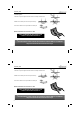
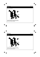
Construction 16. Triac. TR1 : BT137F-600 mm 3 BOLT 10mm M3 BOLT LOCK WASHER M3 NUT Place the heatsink and the triac on the PCB. Fix the two components with a M3 bolt and nut. Now, the triac may be soldered. 7 Construction 16. Triac. TR1 : BT137F-600 mm 3 BOLT 10mm M3 BOLT LOCK WASHER M3 NUT Place the heatsink and the triac on the PCB. Fix the two components with a M3 bolt and nut. Now, the triac may be soldered.
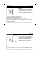
Test & connection 17. Test & connection 110 - 240VAC LL N L M L N ATTENTION: A PART OF THE CIRCUIT IS ALWAYS UNDER MAIN VOLTAGE. TAKE ALL POSSIBLE PRECAUTIONS, SO THAT NO-ONE CAN TOUCH ANY PART. FOR YOUR OWN SECURITY AS FOR THE USERS' SECURITY. MOUNT THIS KIT PREFERABLY IN AN ISOLATING HOUSING. THE FUSE WILL MELT IN CASE OF AN OVERLOAD, REPLACE IT BY EXACTLY THE SAME TYPE. MAINS L N LOAD N N L VAC N Fig 1.0 Connect the load to the screw connector marked by "LOAD" see fig. 1. Consider the max.
Test & connection Turn RV1 completely to the left (minimal position) and RV2 completely to the right. Switch the power on. BE CAREFUL: a large part of the circuit is under mains power, do not touch it! Adjust RV2 so that the motor will have the lowest speed. It is important for the motor to start at any time, even where RV1 is put in its minimal position, otherwise there might be large currents causing sparks that burn the carbon brushes.
PCB PCB 10 PCB PCB 10
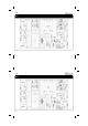
Diagram Schematic diagram 470µF 1µF 11 Diagram Schematic diagram 470µF 1µF 11
VELLEMAN Components NV Legen Heirweg 33 9890 Gavere Belgium Europe www.velleman.be www.velleman-kit.com Modifications and typographical errors reserved © Velleman Components nv. H2636IP - 2004 - ED1 (rev.2) 5 410329 311414 VELLEMAN Components NV Legen Heirweg 33 9890 Gavere Belgium Europe www.velleman.be www.velleman-kit.com Modifications and typographical errors reserved © Velleman Components nv. H2636IP - 2004 - ED1 (rev.