Total solder points: 101 Difficulty level: beginner 1 2 3 4 5 advanced ELECTRONIC WATCHDOG K2655 ders wit es intru r a c s d an . Listens barking realistic ILLUSTRATED ASSEMBLY MANUAL H2655IP'1_rev3.
Features & Specifications Features: Very realistic simulation through the use of a random generator. Choice of two different dogs. Reacts to environment noise, with adjustable sensitivity. Trigger input to connect other detectors (photo-electric cell, motion detector, smoke detector, etc...). Connectable to more powerful amplifier. Complete with rectifier and voltage regulator. Specifications: Power supply : 2x8V/0,5A transformer or 9 to 12VDC. Loudspeaker output (2W at 4 ohm).
Assembly hints 1. Assembly (Skipping this can lead to troubles ! ) Ok, so we have your attention. These hints will help you to make this project successful. Read them carefully. 1.1 Make sure you have the right tools: A good quality soldering iron (25-40W) with a small tip. Wipe it often on a wet sponge or cloth, to keep it clean; then apply solder to the tip, to give it a wet look. This is called ‘thinning’ and will protect the tip, and enables you to make good connections.
Assembly hints 1.3 Soldering Hints : 1- Mount the component against the PCB surface and carefully solder the leads 2- Make sure the solder joints are cone-shaped and shiny 3- Trim excess leads as close as possible to the solder joint AXIAL COMPONENTS ARE TAPED IN THE CORRECT MOUNTING SEQUENCE ! REMOVE THEM FROM THE TAPE ONE AT A TIME ! You will find the colour code for the resistances and the LEDs in the HALG (general manual) and on our website: http://www.velleman.be/common/service.
Construction 1. Jumpers 3. Resistors R... J1 J3 J6 2. Diodes. Watch the polarity ! D1 D2 D3 D4 D5 : : : : : 1N4148 1N4148 1N4148 1N4148 1N4148 D6 : 1N4007 D7 : 1N4007 CATHODE D...
Construction R35 : 100K (1 - 0 - 0 - 3 - 1) (1 - 0 - 0 - 3 - 2) R36 : 100K (1 - 0 - 0 - 3 - 1) (1 - 0 - 0 - 3 - 2) R37 : 100K (1 - 0 - 0 - 3 - 1) (1 - 0 - 0 - 3 - 2) R38 : 100K (1 - 0 - 0 - 3 - 1) (1 - 0 - 0 - 3 - 2) R39 : 51K (5 - 1 - 0 - 2 - 1) (5 - 1 - 0 - 2 - 2) R40 : 51K (5 - 1 - 0 - 2 - 1) (5 - 1 - 0 - 2 - 2) R41 : 51K (5 - 1 - 0 - 2 - 1) (5 - 1 - 0 - 2 - 2) R42 : 51K (5 - 1 - 0 - 2 - 1) (5 - 1 - 0 - 2 - 2) R43 : 51K (5 - 1 - 0 - 2 - 1) (5 - 1 - 0 - 2 - 2) R44 : 51K (5 -
Construction 10. Capacitors 12. Big trimmers. 14. IC’s. Watch the position of the notch! RV... C7 : 100nF / 250V C8 : 100nF / 250V RV1 : 4K7 RV4 : 470K 11. Electrolytic Capacitors. Watch the polarity ! 13. Voltage regulator TRIG level Volume VR... C... C12 : C13 : C14 : C15 : 10µF / 35V 10µF / 35V 220µF / 16V 1000µF / 16V IC1 : LM324 or eq. IC2 : CD4093 or eq. IC3 : CD4040 or eq. IC4 : VK2655 (programmed Eprom 2764C25) IC5 : CD4015 or eq.
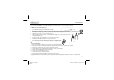
Construction 15. Microphone MIC... MIC Attention : the negative connection is the one closest to the earth lip of the microphone housing. Solder them both together. The remaining pin is the positive connection. Twist the connection wires in order to avoid interferences and noise. Tip : use screened cable (Screen connected to the negative should the connection be too long (0,5m or 2ft). 8 H2655IP'1_rev3.
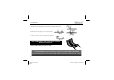
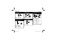
Connecting 16. CONNECTING 1. Hook up when using a transformer Min. 4 ohm Red Black 2x8V/0.5A B GND A Fig. 1.0 9 H2655IP'1_rev3.
Connecting 2. Hook when using a battery : Min. 4 ohm Red Black 9V b atter y Red Black Fig. 2.0 10 H2655IP'1_rev3.
Test & use 17. TEST & USE Turn all the trimmers to their centre position. Connect a loudspeaker of at least 4 ohm to the points LS. Connect the transformer (8V-0-8V) to the points VAC (Fig. 1.0). The center tap (0) should be connected to ground (GND, the middle one of the three VAC pins). The circuit can also be powered with direct current (9 to 12V, unregulated): in this case the negative goes to GND (the middle pin), the positive to one of the two outmost pins A or B (Fig. 2.
Test & use Capacitor C3 takes care that the dog does not go on barking as long as the TRIG contacts are closed. To enable barking the whole time (e.g. with smoke detection), you may replace capacitor C3 by a wire link. With a 4 ohm horn-type loudspeaker, the volume usually will appear sufficient. Should you still want a more powerful amplifier, you may connect it to AF OUT. Pay attention to the polarity! Fit a 100nF MKM capacitor for C16.
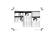
PCB 18. PCB layout. 13 H2655IP'1_rev3.
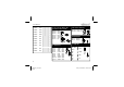
Diagram 19. Diagram 14 H2655IP'1_rev3.
Diagram 15 H2655IP'1_rev3.
Modifications and typographical errors reserved © Velleman nv. H2655IP - 2012 - ED3 H2655IP'1_rev3.