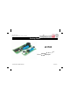
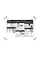
Total solder points: 185 Difficulty level: beginner 1 2 3 4 5 advanced Parking Radar K3502 yes’ or as ‘e , id a g parkin Use as robot projects.
Features & Specifications If you have problems parking then this kit is for you. Using (ultrasonic) sound waves, whose frequency is beyond our range of hearing, we can "measure" a distance. Consequently, a sensor mounted at the back of the car can give an indication of the distance between your car and the car parked behind you or other obstacles (only at the same height as the sensor). When the preset minimum distance is crossed, an audible signal is generated.
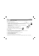
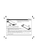
Assembly hints 1. Assembly (Skipping this can lead to troubles ! ) Ok, so we have your attention. These hints will help you to make this project successful. Read them carefully. 1.1 Make sure you have the right tools: • A good quality soldering iron (25-40W) with a small tip. • Wipe it often on a wet sponge or cloth, to keep it clean; then apply solder to the tip, to give it a wet look. This is called ‘thinning’ and will protect the tip, and enables you to make good connections.
Assembly hints 1.3 Soldering Hints : 1- Mount the component against the PCB surface and carefully solder the leads 2- Make sure the solder joints are cone-shaped and shiny 3- Trim excess leads as close as possible to the solder joint REMOVE THEM FROM THE TAPE ONE AT A TIME ! AXIAL COMPONENTS ARE TAPED IN THE CORRECT MOUNTING SEQUENCE ! You will find the colour code for the resistances and the LEDs in the HALG (general manual) and on our website: http://www.velleman.be/common/service.
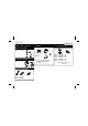
Construction (A) Assembly of the base PCB : P3502B 1. Jumpers 3. Resistors R... J 2. Diodes. Watch the polarity! D1 D2 D3 D4 D5 5. IC sockets, Watch the position of the notch! : : : : : 1N4148 1N4148 1N4148 1N4148 1N4007 CATHODE D... R1 R2 R3 R4 R5 R6 : : : : : : 10M 22K 27K 27K 47 10K (1 - 0 - 6 - B) (2 - 2 - 3 - B) (2 - 7 - 3 - B) (2 - 7 - 3 - B) (4 - 7 - 0 - B) (1 - 0 - 3 - B) IC1 : IC2 : IC3 : IC4 : IC5 : 16p 16p 14p 14p 16p 6. Capacitors 4. Quartz crystal X...
Construction 7. Electrolytic capacitor. Watch the polarity ! 10. Buzzer 11. IC’s mounting 1 C6 : 470µF PIN 1 C... BUZ1 8. Trim Potentiometer RV1 : 470K 9. Screw connectors J1 : 2p + 2p J2 : 2p + 2p 6 RV1 Be sure to put the longest connection into the bore marked ‘+’ IC1 : IC2 : IC3 : IC4 : IC5 : CD4060 or eq. CD4020 or eq. CD4068 or eq. CD4093 or eq. CD4049 or eq.
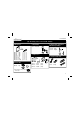
Construction (B) Assembly of the receiver PCB : P3502S 1. Resistors 3. Transistor 5. Electrolytic capacitors. Watch the polarity ! T1 : BC547B R... R7 R8 R9 R10 R11 R12 R13 R14 : 15K : 15K : 15K : 15K : 1K : 1K : 10K : 270K C10 : 10µF C11 : 100µF (1 - 5 - 3) (1 - 5 - 3) (1 - 5 - 3) (1 - 5 - 3) (1 - 0 - 2) (1 - 0 - 2) (1 - 0 - 3) (2 - 7 - 4) C... 4. Capacitors 6. Screw connectors 2. IC socket.
Construction 7. Sensors SENS 1 : MA40A5S or eq.(marked with T). SENS 2 : MA40A5R or eq. (marked with CTD) 8. IC mounting 1 PIN 1 IC6 : TL074 Either on the print or connect them to the soldering terminals, see chapter concerning the installation in the car.
Test 3. TEST Connect the points GND, +V, RW, DIS, S1 and S2 of the main PCB to the corresponding points on the receiver PCB. Make sure that the distance between the receiver print and the base print is approx. 50cm. Adjust the trimmer RV1 at the middle position RV1. Connect a 12VDC power supply (or a battery) between the points GND (-) and +.
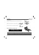
Installation Install the print behind the bores using spacing sleeves, so that the sensors are facing the bores properly without touching the housing. Fig. 1 Fig. 2 B) With the sensors in horizontal position (fig. 2): In this case the sensors are simply mounted on the print. Now realise the gaps in the housing as shown on the drawing 4.0 Install the print behind the bores using spacing sleeves, so that the sensors are facing the bores properly without touching the housing.
Installation FINE WIRE GAUZE SENSOR FINE WIRE GAUZE CASE Fig. 3 SENSOR CASE Close the housing as watertight as possible f.i. by using silicone. Surch for a suitable place somewhere in the trunk, to built in the base print (by preference as close as possible to the sensor, see below) Find a suitable place, approximately in the middle of the backside of the car, for installing the sensors f.i. : underneath or above the bumper.
Connection & use 5. DEFINITIVE CONNECTION Connect the receiver to the base print. Connect the terminal GND of the base print to the - of the car (chassis) Connect the terminal ‘+’ of the base print to the ‘+’ of the reverse light. 6. USE The circuit is activated as soon as the gear is shifted in reverse (this is marked by a 'bip' tone) and will detect any obstacle within the range of the sensors, the detection distance (i.e. the sensitivity) being adjusted by means of the trimmer RV1.
Connection P3502B S1 V D+ GN + P3502S D+ GN V S2 S2 DIS D GN P3502B S1 RW RW DIS + S1 S2 RW D GN +V 13
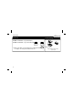
Schematic diagram 7.
PCB 8.
VELLEMAN Components NV Legen Heirweg 33 9890 Gavere Belgium Europe www.velleman.be www.velleman-kit.com Modifications and typographical errors reserved © Velleman Components nv.