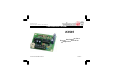
Total solder points: 94 Difficulty level: beginner 1 2 3 4 5 advanced CAR HEADLIGHT ALARM K3505 s due to ad batterie ft on.
VELLEMAN NV Legen Heirweg 33 9890 Gavere Belgium Europe www.velleman.be www.velleman-kit.
Features & Specifications Features: Continuously repeated alarm tone for lights ON (may be disabled) Repeated alarm tone for lights OUT Only 3 wires are required for hook-up Specifications: Supply voltage: 12V battery PCB dimensions: 48 x 57mm (1.9" x 2.
Assembly hints 1. Assembly (Skipping this can lead to troubles ! ) Ok, so we have your attention. These hints will help you to make this project successful. Read them carefully. 1.1 Make sure you have the right tools: • A good quality soldering iron (25-40W) with a small tip. • Wipe it often on a wet sponge or cloth, to keep it clean; then apply solder to the tip, to give it a wet look. This is called ‘thinning’ and will protect the tip, and enables you to make good connections.
Assembly hints 1.3 Soldering Hints : 1- Mount the component against the PCB surface and carefully solder the leads 2- Make sure the solder joints are cone-shaped and shiny 3- Trim excess leads as close as possible to the solder joint REMOVE THEM FROM THE TAPE ONE AT A TIME ! DO NOT BLINDLY FOLLOW THE ORDER OF THE COMPONENTS ONTO THE TAPE.
Construction 1. Jumper 4. Resistors Between IC1 & IC2 2. Diodes. Watch the polarity ! D1 D2 D3 D4 D5 D6 D7 D8 D9 : : : : : : : : : 1N4148 1N4148 1N4148 1N4148 1N4148 1N4148 1N4148 1N4007 1N4007 D... CATHODE 3. Zener diode. Watch the polarity ! ZD1 : 2V4 CATHODE 6. Capacitor. R... ZD... R1 R2 R3 R4 R5 R6 R7 R8 R9 R10 : : : : : : : : : : 47K 47K 47K 47K 220K 470 470 10K 10K 1M (4 (4 (4 (4 (2 (4 (4 (1 (1 (1 - C1 : 100nF (104) 7777277000- 3333411335- B) B) B) B) B) B) B) B) B) B) 7.
Construction 9. Electrolytic Capacitors. Watch the polarity ! C2 C3 C4 C5 C6 C7 : : : : : : 22µF 22µF 22µF 22µF 22µF 470µF 11. IC’s. Check the position of the notch! C... 10. Screw connectors IC1 : CD40106 or eq. IC2 : CD4070 or eq.
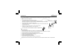
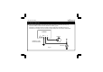
Use and connection 12. Use and connection Mount the circuit underneath the dash board and make the following connections: (see Fig. 1.0) Connect the GND connection with the chassis or the battery (-) pole. Connect the L connection with the connection carrying voltage when the lights are turned on. Connect the C connection with the connection carrying voltage when the contact is switched ON. K3505 J2 GND L C CONTACT WARNING TO TURN LIGHTS ON AND OFF CAR LIGHT Fig. 1.
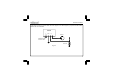
Use and connection If the alarm should only operate when the driver forgets to turn off the lights, a jumper should be inserted between the J2 connections. K3505 J2 GND L C CONTACT WARNING TO TURN LIGHTS OFF ONLY CAR LIGHT Fig. 2.
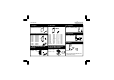
PCB C4 10 D7 C2 C5 D6 C7 IC1 C3 R2 R4 GND BUZ1 D2 R7 IC2 T1 R8 VELLEMAN D5 P3505'1 R5 R6 R9 R10 D1 D3 ZD1 D4 C6 13. PCB layout.
Diagram 14.
Modifications and typographical errors reserved © Velleman Components nv.