Stereo valve power amplifier plifier is wer valve am at now o p h ig h a s u that, so th For most of kit changes is h sound". T .
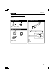
Features & specifications Features: Pure valve sound with high quality EL34 valves. High quality black and chrome housing. Chrome valve socket covers. Easy bias adjustment with LED indication. Removable bottom for easy access and service. High quality capacitors and components. Gold plated input and speaker terminals. Standby function. Soft start circuit for power transformer. Specifications: • • • • • • • 2 x 90Wrms in 4 or 8W. Up to 2 x 15Wrms full class A. Bandwidth: 8Hz to 80KHz (-3dB/1W).
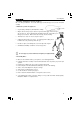
Assembly hints 1. Assembly (Skipping this can lead to troubles ! ) Ok, so we have your attention. These hints will help you to make this project successful. Read them carefully. 1.1 Make sure you have the right tools: • A good quality soldering iron (25-40W) with a small tip. • Wipe it often on a wet sponge or cloth, to keep it clean; then apply solder to the tip, to give it a wet look. This is called ‘thinning’ and will protect the tip, and enables you to make good connections.
Assembly hints 1.
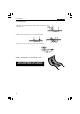
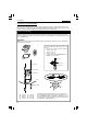
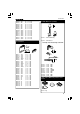
Construction Assembly of the small input PCB P4040i: This PCB is used to connect the input signal (via two RCA sockets) via two holes at the rear of the cabinet. 1. Ceramic Capacitor 3. Shielded wire connector C ... C1 : 47nF (473) 2.
Construction Assembly of the main PCB P4040B: Because of the PCB dimensions, first mount the 8 large tube sockets so that the PCB can rest on a table, without the component leads being touched. When mounting the components, it is best to fold back the component leads a little before turning the PCB over to solder them. 1. Valve socket mounting Check the position of the notch in the centre of the tube socket, it must correspond to the notch in the circle printed on the PCB.
Construction 2. Jumpers. Note that from J1 to J6, two jumper leads have to be mounted in the same hole. TIP : In order to get nice straight wiring, without too much folding and measuring, follow these hints: 3. Jumpers for voltage selection MAINS VOLTAGE SELECTION: For 100V mains input, mount: Mount the lead on the PCB as it is. Solder 1 end of the lead. Then carefully pull on the free end of the lead until it is straight. Now solder the other end.
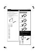
Construction D7 D8 D9 D10 : : : : 1N4007 1N4007 1N4007 1N4007 D11 D12 D13 D14 : : : : 1N5408 1N5408 1N5408 1N5408 D15 D16 D17 D18 D19 D20 D21 D22 D23 D24 D25 D26 : : : : : : : : : : : : 1N4148 1N4148 1N4007 1N4148 1N4007 1N4007 1N4007 1N4148 1N4148 1N4148 1N4148 1N4007 not on tape ! not on tape ! not on tape ! not on tape ! 5. Zener diodes. Watch the polarity! CATHODE ZD... ZD1 : 3V9 ZD2 : 3V9 6. 1/4W Resistors R...
Construction R62 R63 R64 R65 R66 R67 R68 R69 R70 R71 R72 R73 R74 R75 R76 : : : : : : : : : : : : : : : 47K 220 220 820 220 220 820 330K 330K 330K 330K 330K 330K 330K 330K (4 - 7 - 3 - B - 9) (2 - 2 - 1 - B - 9) (2 - 2 - 1 - B - 9) (8 - 2 - 1 - B - 9) (2 - 2 - 1 - B - 9) (2 - 2 - 1 - B - 9) (8 - 2 - 1 - B - 9) (3 - 3 - 4 - B - 9) (3 - 3 - 4 - B - 9) (3 - 3 - 4 - B - 9) (3 - 3 - 4 - B - 9) (3 - 3 - 4 - B - 9) (3 - 3 - 4 - B - 9) (3 - 3 - 4 - B - 9) (3 - 3 - 4 - B - 9) 9. LEDs. Watch the polarity! LD...
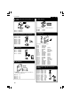
Construction 11. REED relays. Check the position of the notch! 15. DIP switches RY... SW... 1 1 PIN 1 Check that switch 1 corresponds to pin 1. SW2 SW3 RY1 : VR05R121 RY2 : VR05R121 12. Resistors trimmers (vertical type) RV1 RV2 RV3 RV4 RV5 RV6 RV7 RV8 : : : : : : : : 100K 100K 100K 100K 100K 100K 100K 100K : : : : DS-4P DS-4P 16. Capacitors C... RV... Check the minimum voltage ! 13. Transistors T1 T2 T3 T4 : : BC547C BC547C BC547C BC516 14. 5W resistors R...
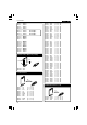
Construction 18. PCB connectors 20. Power relays The various relays have leads that correspond to the printing on the PCB: With the holes facing the PCB edge ! RY3 : VR5V122C RY... SK3 SK4 : 2p : 2p SK9 SK10 SK11 SK12 SK13 SK14 SK15 SK16 : : : : : : : : 2p 2p 2p 2p 2p 2p 2p 2p RY4 RY5 : VR10V121C : VR10V121C RY... 21. Fuse holder + fuse SK5 SK6 SK7 SK8 : : : : 3p 3p 3p 3p F1 F... 19. Valve sockets V... 1 6 2 7 Insert a 5A fuse for 115V Insert a 2.
Construction 23. Electrolytic capacitors (check the polarity) Generally these capacitors are from the snap-in type and cannot be mounted incorrectly. C35 C36 C37 C38 C39 C40 C41 C42 : : : : : : : : 22µF/350V 22µF/350V 100µF/400V 100µF/400V 220µF/450V 220µF/450V 220µF/450V 220µF/450V C... 24. Switch IMPORTANT: Don't leave a gap between the SWITCH and the PCB! SW... SIDE VIEW Mount him as square as possible against the PCB, also solder the metal support. SW1 : 3P ON-ON-ON 25. IC.
Valve wiring 26. 6,3V Valve wiring Wiring for the 8 tube sockets V1 to V8. Use twisted brown wire for each one. For safety, it is advisable to check with an ohmmeter that the two 6.3V terminals are not short circuited. f2 f1 f2 f1 f2 V6 V7 5 6 7 8 3 1 3 4 1 8 6 8 4 7 6 1 3 4 1 8 5 3 2 5 8 1 2 V2 7 4 5 3 5 4 1 8 f1 V3 2 5 4 f1 6.3VAC 6.
Assembly into the unit 27. Assembly into the unit Mount the cage nuts into the square holes concerned, from the inside to the outside, (with the nut along the inside). These nuts are used to fasten the covers down, and there are 7 of them in the cabinet base. CLICK INTO HOLE Fig. 1.0 M3 NUT M3 LOCK WASHER 5mm SPACER Mount the input PCB on the right-hand side of the housing as shown in the figure.
Assembly into the unit Check that the solder side of the PCB, is along the side of the nuts. Solder a 35 cm length of yellow wire to the 4 Ohm connection (YEL). Solder a 35 cm length of red wire to the 0 connection (RED). HINT: In order to tighten the nuts well, immobilise the loudspeaker terminal by inserting a screwdriver through the hole for the loudspeaker lead. Fit the unit onto the housing with three black Allen bolts, fix with a shakeproof washer and nut.
Assembly into the unit Mount the ring core transformers: Stick a adhesive foot to the base of the cabinet, in the middle where each transformer has to be put. METAL CASE RUBBER WASHER Cut 4 x 4 cm TRANSFORMER RUBBER WASHER Fig. 5.0 PLATE BOLT Mount an output transformer on the left-hand side of the housing, see figure 6.0.
Assembly into the unit Twist the previously soldered red and yellow wires together and fit them as shown in the figure, the cable ties supplied can also be used. 8 0 4 OUTPUT TRANSFORMER ZD043 8 0 4 OUTPUT TRANSFORMER ZD043 YELLOW BLUE RED RED BLUE YELLOW Fig. 8.0 Mount the supply transformer in the middle of the cabinet. Ensure that the leads are positioned as shown in the figure 6. The thick grey and green wires must be at the highest point.
Assembly and wiring 28. Assembly and wiring Fit the main PCB into the housing and screw it down with the black Allen bolts along the underside. Connect the mains lead to the screw connector, MAINS, with the blue wire to the N terminal and the brown wire to the L terminal. The short earth wire is connected to the EARTH connector. Connection of the transformers: ! IMPORTANT: The connector leads of the transformer may not be shortened.
Final inspection 29. Final inspection ! ATTENTION: THERE ARE VOLTAGES OF MORE THAN 400V AT MANY POINTS ON THE PCB. Ensure that suitable insulated measuring leads are used. Ensure that no children are in the vicinity. Switch the mains voltage switch to OFF, ie. fully down. Connect the mains connector via a lead to a mains outlet. The plug may have to be changed for your country. In that case, cut off the plug from the lead, and connect an appropriate plug for your country.
Setting - up 30. Setting up Switch off the mains voltage. Turn all trimmer potentiometers, RV1 to RV8, fully anticlockwise. Mount the 8 tubes, V1 to V8, type EL34 (or C6A7, CV1741) into their sockets (check the position of the notch). ! IMPORTANT: Connect an 8.2 Ohm 5W resistor between the output terminals (0 and 8 Ohm) of both channels. The output of a tube amplifier must always be loaded.
Test & final assembly of the cabinet 31. Test The amplifier can now be connected to loudspeakers of 8 or 4 Ohms, the common connection is in the middle. IMPORTANT If 8 Ohm loudspeakers have been connected, then first check that not too much hum can be heard in the loudspeakers, which is why a preamplifier should not yet be connected. Should too much hum be audible, then the output transformer of the channel concerned should be turned a little clockwise or anti-clockwise until the hum weakens.
Final assembly of the cabinet The cabinet can now be completed by first fitting the covers for the supply transformers. Mount the front panel to the cabinet, use the support brackets supplied, together with M3 and M4 Allen bolts. Check the position of the switch and the LED (see figure 13). HOUSING 6mm M3 BUTTON HEAD BOLT LOCK WASHER SUPPORT BRACKET FRONT PANEL 6mm M4 BUTTON HEAD BOLT Fig. 13 If it all fits together well, then all bolts can be fully tightened.
Usage 33. Usage ! WARNINGS. THIS UNIT GETS HOT, KEEP OUT OF REACH AND AWAY FROM CHILDREN. CHECK THAT THE MAINS VOLTAGE CORRESPONDS TO THAT OF THE UNIT. BEfORE OPENING THE UNIT, THE MAINS CORD MUST BE REMOVED IN ORDER TO AVOID ELECTRIC SHOCKS. It is normal for the tubes and cabinet to get very hot, so place the amplifier in a well ventilated area, certainly not in a closed cabinet or rack. We advise to check the standby current adjustment once a year, certainly if the end tubes are new.
N F1 2.5A SLOW @ 230-245VAC 5A SLOW @ 100-120VAC MAINS L A 230 0 100 B 120 C 1N4007 D3 D4 1N4007 RY3 1K R4 470 D5 R3 1N4007 15/5W 15/5W 1N4007 BC547C T1 VR10V121C RY4 1N4148 D2 L-93WEGW LD2 RED 560 1K5 15/5W GREEN R37 LD1 L-56BHD 1N4148 D19 1N4007 D21 R36 D25 15/5W R105 R107 R108 R106 470u C27 7V5 ZD1 OFF C28 470u D20 ON SW1 12VDC 1N4007 D6 1N4007 VR5V122C 1N4148 D1 12VAC/2.
SI GND RY2 100p C2 1K R2 VR05R121A RIGHT INPUT IN 6 7 8 1 14 GREEN 6.3VAC GREEN 2 13 100p C4 12K R16 33K 3 220/.5W f2 220/.5W R67 4 5 1 180 R25 820 R24 1M R26 C5 47u 22K R27 820/.
SI GND RY1 47n C1 1K VR05R121A LEFT INPUT IN R1 6 2 13 7 8 1 14 33K R12 GRAY 6.3VAC GRAY 100p C3 12K R11 f2 220/.5W R64 4 5 6 180 R19 820 R18 1M R20 C9 47u 22K R21 8 7 820/.
SW1 R35 T1 D1 J24 1 3 J25 LD2 LD1 D24 D19 VIOLET GREEN BLACK BLACK BROWN RED LS- ORANGE J7 RY3 YELLOW LS+ F1 SK5 R36 5A SLOW AT 100/120VAC 2.5A SLOW AT 230/245VAC D20 D26 D21 SK5 D25 L R37 1 2 3 SK9...12 D4 J26 5 4 5 4 D6 R38 J4 3 3 1 J8 D2 RY4 C27 C6 R30 3 0.4VDC ORANGE 100V 120V VIOLET 8 1 R99 R97 8 1 R85 J22 R22 4 1 f1 R63 f1 C29 -50VDC 12VAC TRANSFORMER 245V C10 C28 2 V1 0.
VELLEMAN KIT NV Legen Heirweg 33 9890 Gavere Belgium Europe Info ?: http://www.velleman.be Modifications and typographical errors reserved © Velleman Kit nv H4040IP - 2004 - ED1 (rev. 1.