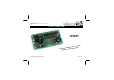
Total solder points: 240 Difficulty level: beginner 1 2 3 4 5 advanced LIGHT COMPUTER K5201 uts d 7 outp n a s rn e nt patt show.
Features & Specifications Features: Sixteen different patterns and 7 outputs provide a unique light show Easy pattern selection with rotary switch Adjustable effect speed External oscillator input Daisy-chain units to create even bigger light shows Special setting for two linked units to create 14 channel operation 7 LED pattern indication Specifications: Power supply : 7.5-9VAC or 12VDC / 250mA Load : 24-240VAC 1.5A/channel max.
Assembly hints 1. Assembly (Skipping this can lead to troubles ! ) Ok, so we have your attention. These hints will help you to make this project successful. Read them carefully. 1.1 Make sure you have the right tools: • A good quality soldering iron (25-40W) with a small tip. • Wipe it often on a wet sponge or cloth, to keep it clean; then apply solder to the tip, to give it a wet look. This is called ‘thinning’ and will protect the tip, and enables you to make good connections.
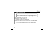
REMOVE THEM FROM THE TAPE ONE AT A TIME ! DO NOT BLINDLY FOLLOW THE ORDER OF THE COMPONENTS ONTO THE TAPE.
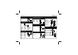
Construction 3. 1. Jumpers 1/4W Resistors J : 5x 4. IC socket. Watch the position of the notch! R... 2. Diodes. Watch the polarity ! D1 D2 D3 D4 D5 D6 D7 D8 D9 D10 D11 D12 : : : : : : : : : : : : 1N4148 1N4148 1N4148 1N4148 1N4148 1N4148 1N4148 1N4148 1N4148 1N4148 1N4148 1N4148 D13 D14 D15 D16 : : : : 1N4007 1N4007 1N4007 1N4007 CATHODE D...
Construction 6. Trimmer 9. Electrolytic Capacitors. Watch the polarity ! 12. LEDs. Watch the polarity! RV1 : 1M C5 : 1µF C6 : 1µF C7 : 1000µF LD1 LD2 LD3 LD4 LD5 LD6 LD7 7. PCB tabs. C... 10. Voltage regulator. Red LD... 23mm 23mm 0.9" CATHODE VR1 : UA7805 L1 L2 L3 L4 L5 L6 L7 N SIG IN. OSC. OUT J1 (X2) RST VR... 8. Transistors.
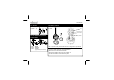
Construction 14. Switch SW2 : 1p 16. Rotary switch. SW... SW3 Nut Internal Tooth Lock Washer 15. ICs. Watch the position of the notch! Stop washer SW... 10 9 8 7 11 12 A 1 2 3 6 5 4 SW... IC1 : NE555 IC2 : CD4024 IC3 : VK5201 (programmed Eeprom 2764C25) The 12-position rotary switch SW3 must be configured for 8 positions. Turn the switch all the way counterclockwise.
Assembly, Hook-up & Use 17. ASSEMBLY, HOOK-UP AND USE Attention : There is no transformer isolating this circuit from the mains. Therefore, all parts of the PCB carry a potentially lethal voltage. The circuit must be mounted in an adapted enclosure according to the applicable norms, so that no live parts can be touched or present any other danger. All wires of the output section must be at least 2.5mm². Power supply wiring can be done with 0.5mm² wire.
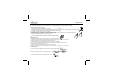
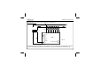
Assembly, Hook-up & Use Hook-up of one unit : Hook-up the unit as shown in the diagram 1.0. N 1.5mm FUSE 0.5mm 2 2 FUSE 50mA SLOW MAINS L 10A 2 1.5mm 7.5...9VAC 0.25A N OSC. OUT GND SIG. IN RST 2 0.5mm RESET L7 L6 L5 L4 L3 L2 K5201 FIG. 1.0 BANK SELECT 7.5...9V L1 PROGRAM SELECT To use the internal speed adjustment, connect ‘OSC OUT’ with ‘SIG IN’ by means of a wire jumper. A external 5V CMOS clock signal (e.g generated by a beat detector), can be connected between GND and SIG. IN.
Assembly, Hook-up & Use Cascading of two units : Two units can be hooked-up in cascade configuration, to create a 14 -channel lightshow. Hook-up both units as shown in the diagram. N 2.5mm 2 FUSE 0.5mm 2 20A 50mA SLOW 0.5mm 2.5mm 7.5...9VAC 0.25A FUSE 2 2 2.5mm N L7 L6 L5 L4 L3 L2 L1 7.5...9VAC 0.25A OSC. OUT SIG. IN RST 0.5mm 2 FUSE 50mA SLOW RESET MASTER K5201 BANK SELECT 7.5...9V L7 0.5mm L5 L4 L3 L2 L1 SLAVE K5201 RESET BANK SELECT PROGRAM SELECT L6 OSC. OUT SIG.
Assembly, Hook-up & Use Do not use a single transformer for both units. Make sure the ‘L’ (live) of both kits is connected to the same phase of the mains. Not doing so will result in damage beyond repair of both kits, and the risk of fire. Use 4mm² wire for the output section and use fuses rated as indicated. Patterns 15 and 16 have been developed for cascade use. Choose pattern 15 for the master unit, and pattern 16 for the slave unit.
Finishing 18. FINISHING When mounting the kit in an enclosure you should make sure the enclosure is sufficiently insulated according to local norms. The complete PCB is best fixed to the front panel of the casing, so that all controls are accessible and the LED's are visible. Make holes in the front panel as shown in figure 3.0. Mount the PCB on the front panel with help of the included bushes and bolts. Place buttons on the spindles of the potentiometer (spindle diameter 5.
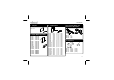
Schematic diagram 19. Schematic diagram.
PCB 20.
VELLEMAN NV Legen Heirweg 33 9890 Gavere Belgium Europe www.velleman.be www.velleman-kit.
01 SOLDERLESS EDUCATIVE STARTERBOX 04 The EDU01 basic experiment kit is the first step into the world of modern electronics. Build your own circuits in a fun, safe and educative way. PICTM TUTOR KIT Enter the world of microcontroller programming, easy step by step instructions. Includes programmer and test board. The Microchip name and logo, PIC, and PICmicro are registered trademarks of Microchip Technology Inc. in the USA and other countries.