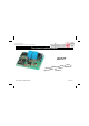
Total solder points: 224 Difficulty level: beginner 1 2 3 4 5 advanced Two channel codelock receiver K6727 ms, rm syste ble la a rm a a comfort lighting, Operate s, etc ... from a rport .
Features & Specifications Features: Easy to build: no coils to be made! Works together with the K6706/K6706A two channel transmitter. For operating garage door. Operating outdoor or indoor lights. Remote control of electrical door locks. Remote control of pool lights or fountain… Two power relays included. Each output selectable for toggle or pulse contact. It is possible to put two receivers in cascade at same location, for four channel output (in combination with two transmitters).
Assembly hints 1. Assembly (Skipping this can lead to troubles ! ) Ok, so we have your attention. These hints will help you to make this project successful. Read them carefully. 1.1 Make sure you have the right tools: • A good quality soldering iron (25-40W) with a small tip. • Wipe it often on a wet sponge or cloth, to keep it clean; then apply solder to the tip, to give it a wet look. This is called ‘thinning’ and will protect the tip, and enables you to make good connections.
Assembly hints 1.3 Soldering Hints : 1- Mount the component against the PCB surface and carefully solder the leads 2- Make sure the solder joints are cone-shaped and shiny 3- Trim excess leads as close as possible to the solder joint REMOVE THEM FROM THE TAPE ONE AT A TIME ! AXIAL COMPONENTS ARE TAPED IN THE CORRECT MOUNTING SEQUENCE ! Velleman hereby certifies that the device K6727 meets the essential requirements and all other relevant stipulations of directive 1999/5/EG and 1995/5/EC.
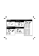
Construction 1. Jumper wires 3. Zener diodes Watch the polarity ! 5. Resistors R... ZD... CATHODE J1 J2 ZD1 : 4V3 ZD2 : 4V7 (5V1) 2. Diodes. Watch the polarity ! 4. SAW resonator. L2 CATHODE D... L...
Construction 6. IC sockets. (check the position of the notch) 8. Capacitors 10. LED’s. Watch the polarity! C... 1 IC... IC1 : 18p IC2 : 18p IC3 : 8p IC4 : 14p 7. Capacitive trimmer C1 C2 C3 C4 C5 C6 C7 C8 C9 C10 C11 : : : : : : : : : : : 1p 2p 22p 82p 330p 330p 330p 330p 100n 100n 100n LD1 (2p2) (331) (331) (331) (331) (104) (104) (104) 9. Transistors 6 3mm Red CATHODE CV... CV1 : 5pF Set the tuning capacitor to around the middle of its adjustment range.
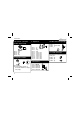
Construction 12. Capacitors. Watch the polarity ! 14. Relays 16. Sticker Affix the supplied sticker to the housing. Velleman RY1 : VR15 RY2 : VR15 C12: 1µ C13: 1µ C14: 470µ RY... 433,92 MHz SRFCE C... 15. ICs. (check the position of the notch) 1 13. Voltage regula- PIN 1 IC... Mind the orientation ! VR...
Personal code 17. Create your code You can select your own code for a transmitter/receiver combination. There is a 9 row jumper island located directly next to IC1 for setting the code. The code is set by connecting one or more code points to a neighboring ‘+’ or ‘-‘ point using the small jumpers. Code points may also be left unconnected (open): see figure.
Operating mode 18. Operating mode By using the jumpers JM1 or JT1, channel 1 of the receiver can be set up for two output possibilities: 1. Output channel 1 is on while the transmitter is pressed (MOMENT), this is mostly used for operating a door lock, garage door, etc. JM1 2. Output channel 1 switches (on/off) every time the transmitter is pressed (TOGGLE), this setting is mostly used for switching alarms in and out, for operating central door locking systems, for switching a lamp on and off, etc.
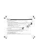
Test & set-up 19. Test and set-up IMPORTANT: • For adjusting the receiver, a completely plastic tuning screwdriver (including plastic blade) is needed. This is supplied with the receiver. • The transmitter must be in its housing with the cover on, and fitted with a new battery type V23GA or GP23A. Check the polarity which is shown in the housing. • The receiver may not be in the vicinity of any metal objects. • The transmitter and receiver must have the same code.
Test & set-up • • • The transmitter must be in its housing with the cover off. Activate the transmitter (do not touch any other parts other than the push button) and then very carefully turn the tuning capacitor CV on the transmitter until the tuning LED of the receiver lights up. If all is well, one of the relays should now switch, if of course the codes of the transmitter and receiver are the same.
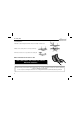
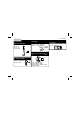
Connection 20. Connection DC supply: CHANNEL 2 RELAY OUTPUT CHANNEL 1 RELAY OUTPUT K6727 NC2 COM2 NO2 NC1 COM1 NO1 VB GND VA AC supply: CHANNEL 2 RELAY OUTPUT CHANNEL 1 RELAY OUTPUT - 12...16VDC + K6727 NC2 COM2 NO2 NC1 COM1 NO1 VB GND VA TRANSFO L 9VAC MAINS 9VAC N Other connections: When using the relay output there is a choice between a normally closed contact (NC) or a normally open contact (NO). The common output is at COM.
Connection 21. Using 2 receivers at the same place K6727 J1 Rx GND J2 J1 & J2 CLOSED ADJUST ONLY THIS RECEIVER K6727 J1 Rx GND J2 J1 & J2 OPEN DO NOT ADJUST THIS RECEIVER From one receiver, the jumpers J1 and J2 must be cut, this receiver must not be adjusted with the transmitter. 22. About the housing The circuit can also be installed in a plastic housing (NOT A METAL BOX) e.g. WCAH2851. Place the housing in a place where there are few metal parts.
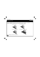
PCB 23. PCB layout.
Diagram 24.
VELLEMAN Components NV Legen Heirweg 33 9890 Gavere Belgium Europe www.velleman.be www.velleman-kit.com Modifications and typographical errors reserved © Velleman Components nv.