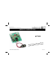
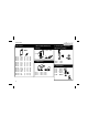
Total solder points: 68 Difficulty level: beginner 1 2 3 4 5 advanced MAINS VOLTAGE DETECTOR K7101 very can be e.
Features & Specifications With this kit one can easily determine whether a wire is live or not. This kit can be used to detect wiring within walls or breaks in cabling. A flashing LED shows whether a current is detected, while the speed at which the LED flashes indicates how close one is to the wiring. For those wanting an audible signal, space is provided on the print for connecting a buzzer type SV4/12.
Assembly hints 1. Assembly (Skipping this can lead to troubles ! ) Ok, so we have your attention. These hints will help you to make this project successful. Read them carefully. 1.1 Make sure you have the right tools: • A good quality soldering iron (25-40W) with a small tip. • Wipe it often on a wet sponge or cloth, to keep it clean; then apply solder to the tip, to give it a wet look. This is called ‘thinning’ and will protect the tip, and enables you to make good connections.
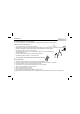
Assembly hints 1.3 Soldering Hints : 1- Mount the component against the PCB surface and carefully solder the leads 2- Make sure the solder joints are cone-shaped and shiny 3- Trim excess leads as close as possible to the solder joint AXIAL COMPONENTS ARE TAPED IN THE CORRECT MOUNTING SEQUENCE ! REMOVE THEM FROM THE TAPE ONE AT A TIME ! You will find the colour code for the resistances and the on our website: http://www.velleman.be/common/service.
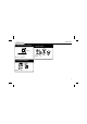
Construction 1. Resistors R... 2. Zenerdiode. Watch the polarity ! 4. Electrolytic Capacitors. Watch the polarity ! ZD1 : 3V9 CATHODE C... R1 : 4M7 R2 : 4M7 R3 : 8K2 R4 : 47K R5 : 470 R6 : 3K3 R7 : 330 R8 : 330 R9 : 27K R10 : 330K R11 : 1M5 R12 : 4M7 R13 : 1K R14 : 10K 6 (4 - 7 - 5 - B) (4 - 7 - 5 - B) (8 - 2 - 2 - B) (4 - 7 - 3 - B) (4 - 7 - 1 - B) (3 - 3 - 2 - B) (3 - 3 - 1 - B) (3 - 3 - 1 - B) (2 - 7 - 3 - B) (3 - 3 - 4 - B) (1 - 5 - 5 - B) (4 - 7 - 5 - B) (1 - 0 - 2 -B) (1 - 0 -3 - B) ZD... 3.
Construction 6. LED. Watch the polarity! 8. Push button 17mm LD1 : 5mm red SW1 : 1p 7.
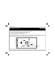
Testing and tuning 9. TESTING AND TUNING Connect a 9V battery to the holder. Stand at a location which is certain to have no mains cabling in the vicinity. Turn the RV1 potentiometer completely to the left (counterclockwise). Push on the button. Normally the LED should briefly light up. Adjust RV1 so that the LED is just about dimmed. The circuit is now adjusted and in its most sensitive position. If one wishes to decrease the circuit's sensitivity, one must turn the potentiometer back to the left.
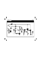
Diagram 10.
PCB 11.
VELLEMAN Components NV Legen Heirweg 33 9890 Gavere Belgium Europe www.velleman.be www.velleman-kit.com Modifications and typographical errors reserved © Velleman Components nv.