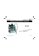
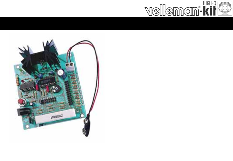
Total solder points: 205 Difficulty level: beginner 1 2 3 4 5 advanced UNIVERSAL BATTERY CHARGER / DISCHARGER K7300 NiCd g of both in g r a h tic (dis)c batteries.
Features & Specifications Specifications: Many battery chargers are available on the market, but few of them are universal chargers that can be used for all battery types. Using our kit, batteries of different voltages and capacities can be charged both quickly and normally. In order to ensure that the battery is fully discharged prior to charging, an automatic discharger is also fitted.
Assembly hints 1. Assembly (Skipping this can lead to troubles ! ) Ok, so we have your attention. These hints will help you to make this project successful. Read them carefully. 1.1 Make sure you have the right tools: • A good quality soldering iron (25-40W) with a small tip. • Wipe it often on a wet sponge or cloth, to keep it clean; then apply solder to the tip, to give it a wet look. This is called ‘thinning’ and will protect the tip, and enables you to make good connections.
Assembly hints 1.
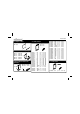
Construction 1. Jumper wires 4. 1/4W Resistors R... J (2x) 2. Diodes. Watch the polarity ! D1 : 1N4148 D2 : 1N4148 D3 : 1N4148 CATHODE D... D4 : 1N4007 D5 : 1N4007 3. Zenerdiode. Watch the polarity ! ZD1 : 6V2 ZD2 : 12V0 CATHODE ZD...
Construction 6. Trim potentiometer 9. Capacitors. 12. Pin headers RV1 RV1 : 220K J1 J2 J3 J4 J5 J6 C... 7. IC sockets. Watch the position of the notch ! IC1 : 14p IC2 : 16p C1 : 47nF (473) C2 : 47nF (473) : : : : : : 2p 3p 8p 8p 12p 12p 10. Transistor 13. 10W resistors T1 : BC557B R38 : 10 8. 1W Resistor 2mm R... 11. Reference Diode 14. DC- Jack VR1 : LM385Z-2.5 2mm R37 : 270 R... VR...
Construction 15. Electrolytic Capacitors. Watch the polarity ! C3 C4 : 1µF : 10µF 18. Push button 20. LEDs Watch the polarity! SW1 : start LD1 : Red LD2 : Green C... CATHODE LD... Mounting into a housing : 16. Power transistor T2 : BD237 19. Electrolytic Capacitor. Watch the polarity ! C5 : 1000µF Mount these LEDs through the housing using the supplied holders and by extending the leads. C... 17.
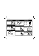
Construction 21. Power transistor 10mm M3 BOLT 23. Adjusting the built-in clock. METAL SIDE Mount a shunt over the CAL connection. LOCK WASHER M3 NUT T3 : BD676 22. IC. Watch the position of the notch! IC1 : CD4536 IC2 : LM324 Mount a shunt over the 52 min selection (quick charge setting). h 14 ' 52 h 14 ' 52 Mount a shunt over the 1.2V selection (charge a 1.2V battery). Connect a DC mains adapter of 15V/800mA (ex. PS1508). Check that the "-" is on the outside edge of the connector.
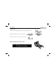
Connection 24. CONNECTION Connect a battery to the ACCU + and - connection. One of the battery holders from our range can be used such as: • • • • • Type BH9V for 1 9V cell. Type BH322B for 2 AA cells (penlight). Type BH341B for 4 AA cells. Type BH363B for 6 AA cells. Type BH383B for 8 AA cells. + + Type BH322B DC adapter of 15V/800mA (ex.
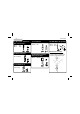
Normal charge (14h) 25. USE WITH NORMAL CHARGE (14h) • Mount a shunt over the 14h position. • Select the battery voltage to be connected using a shunt on the 1.2V to 9.6V connection. • Select the charge current with a shunt between 15mA and 750mA. The charge current of a battery can be determined by dividing the battery capacity by 10 (then select the closest to the charge current). ex. : A battery with a capacity of 500mA/h should be charged with a current of 50mA, thus choose 55mA.
Fast charge (52 mins) 26. FAST CHARGE (52 mins) • Mount a shunt over the 52 min position. • Select the battery voltage to be connected using a shunt on the 1.2V to 9.6V connection. • Select the charge current with a shunt between 15mA and 750mA. The charge current of a battery can be determined by dividing the battery capacity by 10 (then select the closest to the charge current). ex. : A battery with a capacity of 500mA/h should be charged with a current of 50mA, thus choose 55mA.
Fast charge (52 mins) NOTE: Only use the quick charge facility in the event of an emergency, as this type of charging can reduce the battery lifetime. Never mix batteries of different capacities. Never select two voltages or current settings simultaneously.
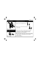
PCB 27. PCB layout.
Diagram 28.
VELLEMAN Components NV Legen Heirweg 33 9890 Gavere Belgium Europe www.velleman.be www.velleman-kit.com Modifications and typographical errors reserved © Velleman Components nv.