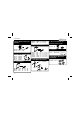
Total solder points: 57 Difficulty level: beginner 1 2 3 4 5 advanced MULTIFUNCTION RELAY MODULE K8008 ing ns includ val, o ti c n fu ter rent 14 Diffe hing, flashing, in c it .. w ..
Features & Specifications Features: 15 different functions including timers, switching, flashing, interval, random switching, … Two pre-programmed delays. Learning mode for delays of 2s up to 12 days. Pushbutton control (with home modular light system K8006). EEPROM for delay time storage in case of power failure. On-board transient filter for relay contacts or load (selectable).
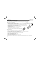
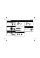
Assembly hints 1. Assembly (Skipping this can lead to troubles ! ) Ok, so we have your attention. These hints will help you to make this project successful. Read them carefully. 1.1 Make sure you have the right tools: • A good quality soldering iron (25-40W) with a small tip. • Wipe it often on a wet sponge or cloth, to keep it clean; then apply solder to the tip, to give it a wet look. This is called ‘thinning’ and will protect the tip, and enables you to make good connections.
Assembly hints 1.3 Soldering Hints : 1- Mount the component against the PCB surface and carefully solder the leads 2- Make sure the solder joints are cone-shaped and shiny 3- Trim excess leads as close as possible to the solder joint REMOVE THEM FROM THE TAPE ONE AT A TIME ! AXIAL COMPONENTS ARE TAPED IN THE CORRECT MOUNTING SEQUENCE ! You will find the colour code for the resistances and the LEDs in the HALG (general manual) and on our website: http://www.velleman.be/common/service.
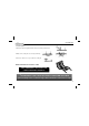
Construction 1. Zener diodes. Watch the polarity ! R4 : 120K (1 - 2 - 4 - B) R5 : 10K (1 - 0 - 3 - B) 6. IC socket. Watch the position of the notch! 4. Metal film resistors ZD... CATHODE IC1 : 8p R... 7. Capacitor ZD1 : 5V1 - 500mW ZD2 : 24V - 1,3W 2. Diodes. Watch the polarity ! D1 D2 D3 D4 D5 : : : : : 1N4148 1N4007 1N4007 1N4007 1N4007 CATHODE D...
Construction 9. Transistor. 12. Capacitor 14. Relay T1 : BC547B RY... C5 10. Pin header : 100nF / 250V Choose operating voltage : SK1 : 3p For 220-245VAC : C4 : 470nF/400VAC For 110-125VAC : 11. Electrolytic Capacitors. Watch the polarity ! RY1 : VR10V241C or eq. 15. IC. Watch the position of the notch! IC1 : VK8008 Programmed PIC12CE518 C4 : 1µF/250VAC 13. VDR C2 : 100µF C3 : 100µF C...
Construction 16. Shunt for transient suppressor. The unit is equipped with a transient suppressor to reduce sparking. Normally, this suppressor is put over the relay contacts. In some cases it might be necessary to put it on the load (eg. with very small loads).
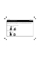
Operation modes 17. Operation mode SW1 OPERATION MODE DESCRIPTION Momentary mode The load will be switched on as long as the pushbutton is pressed. Applications : doorbell, … Toggle mode Push once to turn on, push again to turn off the load. Applications : put a virtually unlimited number of pushbuttons in parallel to control a light source or other device. Start/stop timer Push to turn on. After pre-set time has elapsed, load will turn off. Push any time to turn off.
Operation modes 10 Non-retriggerable timer Push to turn on. After pre-set time has elapsed, load will turn off. Pushing the button during on-time has no effect. Load will turn off when pushbutton is held down and time elapses. Applications : General timing. Turn-on delay Turn on delay starts when button is pushed. When time elapses, load is turned on until button is released.
Operating mode Blinking circuit with timer Push to start the blinking action as described above. At release, the timer will start. When time elapses, the load is turned off. A push during on-time restarts the timer. Applications : warning lights, buzzers, … Random timer As long as the button is closed, the system will activate the output in a random manner (9 minutes to 2.5h between every transition). Initial load status at activation is also determined at random.
Learning mode 18. Learning mode The learning mode allows you to store two different delays, each from 2s up to 12 days. The delays are called delay1 and delay2. Originally, delay1 has been factory set to 3 minutes, while delay2 has been set to 30 minutes. All timer modes use delay1, unless the mode uses both delays. You can change these delays to suit your needs. The new delays are stored in EEPROM, and will be kept in case of a power failure.
PCB 19.
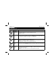
Diagram 20. Diagram SK2 1 2 3 VR10V241C RY1 D1 1N4148 R9 LD1 330K/0.6W 1 VDD C4 470n/250V~ R10 GP5/OSC1/CLKIN GP4 2 3 47K R1 1N4007 1N4007 D4 D5 ZD2 3K9 C2 1N4007 1N4007 14 24V/1.3W 100µ/35V SW1 ZD1 C3 5V1/0.5W 100µ/35V C1 100n R4 R5 10K R2 D3 R3 47K LED3RL 120K 7 6 5 4 D2 VSS 8 R6 220/0.6W GP0 GP1 GP3/MCLR GP2/T0CKI 330K/0.6W IC1 PIC12CE518 SW DIP-4 4 R7 220/0.6W 220/0.
VELLEMAN Components NV Legen Heirweg 33 9890 Gavere Belgium Europe www.velleman.be www.velleman-kit.com Modifications and typographical errors reserved © Velleman Components nv. H8008IP - 2004 - ED2 (rev. 1.