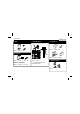
Total solder points: 29 Difficulty level: beginner 1 2 3 4 5 advanced 3,5A SUPPRESSED DIMMER K8026 scent incande r fo r e r motors Dimm collecto d n a s light bulb ILLUSTRATED ASSEMBLY MANUAL H8026IP-1
Features & Specifications Features: Dimmer for incandescent lightbulbs and collector motors. protected against induction voltage peaks. Suppressed according to EN55015. Specifications: AC power : 110-125 or 220-240VAC 50/60Hz. Max. load : 3.5A (750W/220V; 375W/110V). Dimensions: 60x60x40 mm (2.4”x2.4”x1.6”).
Assembly hints 1. Assembly (Skipping this can lead to troubles ! ) Ok, so we have your attention. These hints will help you to make this project successful. Read them carefully. 1.1 Make sure you have the right tools: • A good quality soldering iron (25-40W) with a small tip. • Wipe it often on a wet sponge or cloth, to keep it clean; then apply solder to the tip, to give it a wet look. This is called ‘thinning’ and will protect the tip, and enables you to make good connections.
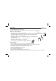
Assembly hints 1.3 Soldering Hints : 1- Mount the component against the PCB surface and carefully solder the leads 2- Make sure the solder joints are cone-shaped and shiny 3- Trim excess leads as close as possible to the solder joint REMOVE THEM FROM THE TAPE ONE AT A TIME ! AXIAL COMPONENTS ARE TAPED IN THE CORRECT MOUNTING SEQUENCE ! You will find the colour code for the resistances and the LEDs in the HALG (general manual) and on our website: http://www.velleman.be/common/service.
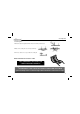
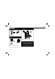
Construction 1. Diac. 3. Potentiometer 4. Capacitors (5 - 6 - 2 - B) FOR 110/125V ONLY : R2 : 220K (2 - 2 - 4 - B) P8026'1 C1 SK1 4A SLOW N R1 : 5K6 F1 R... Jumper wire L R1 LOAD L1 R2 2. Resistor VELLEMAN TR1 RV1 C2 C1 : 100nF (104) D1 D1 : D0200 or eq. HIGH VOLTAGE RV1 RV1 : 470K C2 : 100nF / 250VAC 5. Terminal block Use supplied jumper wire to connect as shown.
Construction 6. Fuse holder + fuse F... 8. Triac 10mm M3 BOLT F1 (4A T) M3 NUT 7. Coil TR1 : TIC225M or eq. L... L1 : 1,5mH / 1KHz. - 4A Important : Put an extra layer of solder on all pre-thinned PCB tracks, to improve their current handling capabilities.
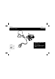
Hook-up 9. Hook-up example ! 380W /110V 750W /240V M AX WARNING : All parts carry lethal voltages! Do not touch while operating. Use an isolated enclosure knob.
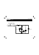
Schematic diagram 10. Schematic diagram. 60W ... 750W @ 230VAC 30W ...
PCB 11.
VELLEMAN Components NV Legen Heirweg 33 9890 Gavere Belgium Europe www.velleman.be www.velleman-kit.com Modifications and typographical errors reserved © Velleman Components nv.