Total solder points: 145 Difficulty level: beginner 1 2 3 4 5 advanced MULTIFUNCTIONAL DIMMER K8028 SE NOI SSED PRE ING TO P U S D OR 15 ACC EN550 ILLUSTRATED ASSEMBLY MANUAL H8028IP'2-rev3.
Features & Specifications Specifications: Microprocessor technology. 13 operating modes including toggle switch, dimmer, staircase timer, slow-on / slow-off dimmer, timer, etc… Suited for both resistive and inductive loads: (Incandecent lightbulbs, halogen lighting, low voltage halogen lighting with wirewound transformers, …) “Soft start”-function stretches bulb life. Auto shutdown-function switches off the unit when a load error is detected (e.g. too inductive or no load).
Assembly hints 1. Assembly (Skipping this can lead to troubles ! ) Ok, so we have your attention. These hints will help you to make this project successful. Read them carefully. 1.1 Make sure you have the right tools: A good quality soldering iron (25-40W) with a small tip. Wipe it often on a wet sponge or cloth, to keep it clean; then apply solder to the tip, to give it a wet look. This is called ‘thinning’ and will protect the tip, and enables you to make good connections.
REMOVE THEM FROM THE TAPE ONE AT A TIME ! DO NOT BLINDLY FOLLOW THE ORDER OF THE COMPONENTS ONTO THE TAPE. ALWAYS CHECK THEIR VALUE ON THE PARTS LIST! H8028IP'2-rev3.
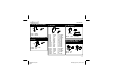
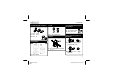
Construction 1. Diodes. Watch the polarity ! 3. Resistors 4. 1W Resistor. R... CATHODE R... D... D1 : 1N4007 D2 : 1N4148 D3 : 1N4148 2m m 2. Zener diode. Watch the polarity ! CATHODE ZD... ZD1 : 12V / 1.
Construction 6. Transistors. 9. Capacitors. T1 : BC547B T2 : BC547B T3 : BC547B 8. Capacitor. C1 : 680nF/600V X1 : 8MHz. C... 7. Voltage Regulator. VR1 : UA78L05 11. Quartz crystal VR... C3 : C4 : C5 : C6 : C7 : C8 : C9 : C11 : 100nF (104) 100nF (104) 10nF (103) 100nF/250V~ 15pF (15) 15pF (15) 100nF (104) 10nF (103) X... 12. LED’s. Watch the polarity ! COLOR= 2...5 LD... CATHODE 10. Electrolytic Capacitors.
Construction 13. Terminal block connectors. 15. Coil. 17. Fuseholder & Fuse. Watch the position ! L... F1: Holder, F/CH45 Fuse: 2.5A, slow. SK1 : 2 x 2p SK2 : 2 x 2p L1: 1mH (Max 2,5A) SK3 : 2p 16. Triac. M3 NUT 18. IC, Check the position of the notch! LOCK WASHER 14. Pushbutton. IC1: VK8028 (programmed µC:PIC16C58 or Eq.) 10mm M3 BOLT TR1: TIC225M, BT137-600E (or eq.) IC2: 24C02 or Eq. = Serial EEPROM. SW1: S500N 7 H8028IP'2-rev3.
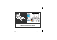
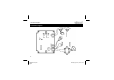
H8028IP'2-rev3.pub page 8 SEC PRIM LOW VOLTAGE HALOGEN BULB. MAINS PUSHBUTTON (S) SK3 SK1 INCANDECENT LIGHTBULB INPUT AC POWER LD4 SK2 MIN DOWN LD3 LD1 LD2 MAX UP.
Connection and test 19. Connection and test Note: this kit operates on mains voltage, which is hazardous. Ensure that it is not connected to mains when working on the PCB or when connecting one or more pushbuttons. Connect the PCB according to the diagram on page 8 First connect the lighting points to the output connector “LOAD”. Finally, low voltage incandescent bulbs or low voltage halogen lamps can be connected using ferromagnetic (wound) transformers. For the speed control function (Function No.
Connection and test Number of flashes Possible cause: Input pushbutton/switch pressed during start up When using a switch this is normal, this fault is not fatal. Some functions are started up with a closed contact. Error in the voltage zero-cross circuit Check the zero-cross circuit, this consists of the following components: R17, R18, R19, C11, D3,T3. The mains frequency must be 50 or 60Hz. EEPROM read and/or write instruction failed. Check the position of the EEPROM (IC2).
Functions 20. Functions No. ( = off = on ) LD4-LD3-LD2-LD1 Function 1 On/off switch. 2 Pushbutton dimmer with memory. 3 Slow ON dimmer (switch controlled). 4 Slow OFF dimmer (switch controlled). 5 Slow ON/OFF (switch controlled). (Equal to the operation of our former K2657). 6 7 8 Soft on/off switch with dimmer and preferred light intensity memory. 9 Same as function 8, but without memory.
Functions 13 14 15 Speed control for synchronous motors. “Learning mode”, to learn delay times. Resets the K8028, according to the standard factory settings. 12 H8028IP'2-rev3.
Selections 21. Details of selections : The various functions are discussed in detail here. For each function it states how the module is controlled: either by one or more parallel switched pushbuttons or by a make contact originating from a single pole switch or a switch output of a time clock. These are connected to the “INPUT” connector. Function 1: On/Off switch: One short press on the pushbutton switches the lighting on, the next press switches it off again.... (=teleruptor connection).
Selections Function 3: Slow “ON” dimmer: Enables the lighting point to be slowly dimmed “ON”, from 0 to max. As long as the “INPUT” contact is closed, the light intensity will continue to increase. After the max. light intensity has been reached, its condition will remain unchanged. The time that the light requires to reach its max. light intensity (DELAY1) is set via FUNCTION 14. Control: Through a make contact. Application: Greenhouse, etc.
Selections Function 6: Repeat slow “ON” and “OFF” dimmer: Enables the lighting point to repeatedly come on and go off slowly. As long as the “INPUT” contact is closed, this process will continue to repeat itself. The time between “OFF” and max. light intensity (“ON” dimming time) = DELAY1. The time between max. light intensity and “OFF” (“OFF” dimming time) = DELAY2. Control: Through a make contact. Application: Lighting for atmosphere, etc.
Selections Function 8: “Soft” on/off switch with dimmer and preferred light intensity memory. With repeated short presses the light will “gently” come on and go out. This is always done within a time span of 5 secs. If the pushbutton is pressed briefly during the “ON” dimming phase, then the light will continue at its current light intensity. The light intensity at this moment is saved as the preferred light intensity.
Selections Function 11: Switch, slow on/off and dimmer combination. This is one of the most complete functions that the module contains. Starting from the rest state this setting has the following functions: On / off switch: For this press briefly (< 1 sec) on the pushbutton. The lighting point is alternately switched on and off at full intensity. Slow ON / OFF: Press for a period between 1.5 and 3 secs on the pushbutton. This activates the slow ON / OFF setting.
Selections Function 13: Speed control for synchronous motors. Only connect synchronous motors when using this function, other loads could damage the module or the connected unit ! Synchronous motors are mainly used for fans. The speed of these motors cannot be changed efficiently by phase chopping, only by proportional control. It works by passing and then blocking proportionate periods of the sinusoidal mains voltage.
Selections Function 14: Learning mode The learning mode enables the time periods DELAY1 and DELAY2 to be set. When this function has been selected, LD4 will flash slowly. Now keep the pushbutton on the PCB (SW1) pressed in, LD3 will light up as an indication. When SW1 is released, the first period (DELAY1) starts to register. LD2 and LD3 now flash alternately to indicate that the registration clock is running. Now wait until the desired time has lapsed.
Selections Function 15: Restore factory settings. If this function is selected, LD1 & LD4 will flash alternately. Keep SW1 (pushbutton on the PCB) pressed in order to restore the factory settings. LD1 will continue to light up for a period of 3 seconds while the standard values (DELAY1 = 3 min., DELAY2 = 1 min., FUNCTION 1) are saved to the EEPROM memory.
Fault code tabel 22. Fault code table Fault code: (number of LED flashes.) Fault: Possible cause: 5 Fault in the voltage zero-cross circuit - Fault on the lighting net work - K8028 faulty. 6 Fault in the current zero-cross circuit - Load too small or not connected - Load fuse blown - K8028 faulty. 7 Phase shift fault! Measured phase shift outside the limit value. - Load too inductive - Unloaded transformer. 8 Phase shift fault! ( The triac cannot be triggered.
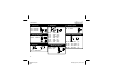
PCB 23. PCB layout. 22 H8028IP'2-rev3.
Diagram 24. Diagram 23 H8028IP'2-rev3.
01 05 SOLDERLESS EDUCATIVE STARTERBOX The EDU01 basic experiment kit is the first step into the world of modern electronics. Build your own circuits in a fun, safe and educative way. 02 SOLAR ENERGY EXPERIMENT KIT USB TUTOR BOARD Learn how to connect your computer with the outside world, master the USB communication with tutorial examples. Play with LED indicators and learn how to drive LCDisplays. 06 SCOPE EDUKIT Fun solar powered projects. Learn all about solar energy.