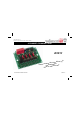
Total solder points: 115 Difficulty level: beginner 1 2 3 4 5 advanced 4 CHANNEL RUNNING LIGHT K8032 ht ffects, lig e t h g li disco creating djustable. r fo l a e Id speed a ctive loads.
Features & Specifications Features: Adjustable speed. Suited for inductive loads. 4 channels with LED indicator. Ideal for disco effects. Noise suppressed according to EN55015. Specifications: AC Power : 110 to 240 VAC. Auto frequency detection : 50/60Hz. Max load per channel 2A : 200W (110 - 125VAC) 400W (220 - 240VAC) Adjustable speed : 0,2 to 3Hz.
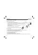
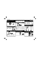
Assembly hints 1. Assembly (Skipping this can lead to troubles ! ) Ok, so we have your attention. These hints will help you to make this project successful. Read them carefully. 1.1 Make sure you have the right tools: • A good quality soldering iron (25-40W) with a small tip. • Wipe it often on a wet sponge or cloth, to keep it clean; then apply solder to the tip, to give it a wet look. This is called ‘thinning’ and will protect the tip, and enables you to make good connections.
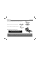
Assembly hints 1.3 Soldering Hints : 1- Mount the component against the PCB surface and carefully solder the leads 2- Make sure the solder joints are cone-shaped and shiny 3- Trim excess leads as close as possible to the solder joint REMOVE THEM FROM THE TAPE ONE AT A TIME ! AXIAL COMPONENTS ARE TAPED IN THE CORRECT MOUNTING SEQUENCE ! You will find the colour code for the resistances and the LEDs in the HALG (general manual) and on our website: http://www.velleman.be/common/service.
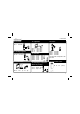
Construction 1. Zener diode. Watch the polarity ! R8 : 270 R9 : 270 (2 - 7 - 1 - B) (2 - 7 - 1 - B) 4. Metal film resistors ZD... CATHODE R... C3 C4 C6 C7 : : : : 100nF 100nF 100pF 10nF (104) (104) (101) (103) 7. LEDs. Watch the polarity! ZD1 : 12V0 2. Diodes. Watch the polarity ! D1 : 1N4007 D2 : 1N4007 6. Capacitors CATHODE D...
Construction 9. Transistor. 12. Capacitors 15. Triacs. T1 : BC547B TR... C8 C9 C10 C11 10. Voltage regulator : : : : 10nF / 600V 10nF / 600V 10nF / 600V 10nF / 600V TR1 TR2 TR3 TR4 13. PCB tabs. VR1 : UA78L05 VR... 11. 1W Resistors R... SK1 SK2 SK3 SK4 SK5 : : : : : Power OUT1 OUT2 OUT3 OUT4 (2x) (2x) (2x) (2x) (2x) : : : : TIC225M TIC225M TIC225M TIC225M The back side corresponds to the thick line! 16. Fuse holder + fuse 14. Electrolytic Capacitors.
Construction 17. Capacitor 19. Hook - up & use 200W at 110-125VAC 400W at 220-240VAC MAX ! For each channel. C1 : 680nF / 600V O 18. IC. Watch the position of the notch! OU IC1 : VK8032 Programmed PIC12C508A Inspect the complete assembly once more before applying power to the unit ! 8 AC AC PLUG PO N W ER OU L T1 L T2 N L T 3 L N OU U T4 N L N Solder an AC cable to the SK1 pins (AC Power). Solder the cables of each lampholder to the appropriate pins.
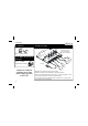
PCB 20.
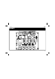
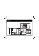
Diagram 21. Diagram LD1 4x TIC225M R6 270 LD2 R7 270 TR1 LD3 R8 270 TR2 LD4 R9 RV1 100KSHS 1N4007 ZD1 ZB12V0 C2 220µ/25 C3 100n C4 100n C5 10µ C6 100pF C7 10n GP2/T0CKl R11 GP3/MCLR/Vpp 47/.6W 10n /600 T1 BC547 D2 1N4007 C8 47/.6W 10n /600 GP1 2 GND D1 TR4 R10 5 3 VR1 UA78L05 I O GP0 6 4 R1 220/1W Vdd R3 220K/.6W 7 R5 470K/.6W GP4/OSC2 GP5/OSC1/CLKIN IC1 PIC12C508A Vss R4 3K3 8 F1 2A 1 R2 220K/.
VELLEMAN Components NV Legen Heirweg 33 9890 Gavere Belgium Europe www.velleman.be www.velleman-kit.com Modifications and typographical errors reserved © Velleman Components nv.