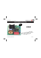
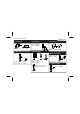
Total solder points: 126 Difficulty level: beginner 1 2 3 4 5 advanced POWER DIMMER (1KW @ 230V) ISE NO SSED O PRE G T SUP ORDIN 5 1 C AC EN550 K8038 h power ig h r e ll r o tr emory fo icrocon Class m non volatile m .
Features & Specifications Specifications: Class microcontroller high power dimmer, suitable for incandescent lamps, mains voltage halogen lighting and low voltage halogen lighting in combination with a conventional (wire wound) transformer. Easy pushbutton operation for dimming of light sources. Phase control can be disabled. Non volatile memory for last set light intensity.
Assembly hints 1. Assembly (Skipping this can lead to troubles ! ) Ok, so we have your attention. These hints will help you to make this project successful. Read them carefully. 1.1 Make sure you have the right tools: • A good quality soldering iron (25-40W) with a small tip. • Wipe it often on a wet sponge or cloth, to keep it clean; then apply solder to the tip, to give it a wet look. This is called ‘thinning’ and will protect the tip, and enables you to make good connections.
REMOVE THEM FROM THE TAPE ONE AT A TIME ! DO NOT BLINDLY FOLLOW THE ORDER OF THE COMPONENTS ONTO THE TAPE.
Construction 1. Diodes. Watch the polarity ! D1 : 1N4148 D2 : 1N4148 D3 : 1N4007 CATHODE D... R13 : 470K (4 - 7 - 4 - B - 9) R14 : 100K (1 - 0 - 4 - B - 9) R15 : 470K (4 - 7 - 4 - B - 9) 5. IC - socket. Watch the polarity ! 4. Resistors R... IC1 2. Zenerdiodes. Watch the polarity ! ZD1 : 12V0 ZD2 : 5V6 CATHODE ZD3 : 5V1 ZD4 : 5V1 ZD... 3. Metal film resistors R...
Construction & connection 7. 1W resistor. 9. Transistors. R... 4mm R19 : 220 T1 : BC547B T2 : BC547B T3 : BC547B (2 - 2 - 1 - B) 8. LEDs. Watch the polarity! 11. Capacitor C12 : 100nF/275VAC 10. Pin headers 12. Electrolytic Capacitors. Watch the polarity ! C2 : 220µF C3 : 100µF LD... C ... CATHODE LD1 : Red LD2 : Yellow (Error) (Status) JP1 : 2 pins JP2 : 2 pins JP3 : 2 pins Mount the 3 shunts ; for their use: see pag. 9 - 10. 6 13. Quartz crystal X...
Construction 14. Terminal blocks 16. Capacitor 18. Coil. SK3 (pushbutton) Choose operating voltage : For 110 - 125VAC : L1 : 1mH / 5A C1 : 1µF / 250V For 220 - 240VAC : 19. IC, Check the position of the notch! C1 : 0,47µF / 600V SK1 (AC POWER) SK2 (LOAD) 15. Fuse + fuse holder F1 : 5A slow 17. Triac mm LT 10 BO M3 CK ER LO ASH W M3 T NU F...
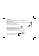
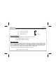
Connection 20. Connection 1. Connect the K8038 according to the wiring diagram. L Mains N N SK3 L Pushbutton(s) Low voltage halogen bulb Incandecent lightbulb Fig. 1.
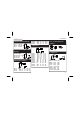
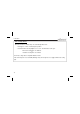
Connection 2. Mount the jumpers on JP1,2,3 or leave them out according to the functions that have to be available. JP1 Enable memory function JP2 Disable phase control JP3 Protection timers on Fig. 2.0 JP1 – Memory function: The last used brightness setting is memorized if this function is activated. Removed: Memory function is deactivated. or Installed: Memory function is activated. JP2 – Phase control: Phase control is needed to control an inductive charge, such as a transformer.
Connection JP3 – Security Timers: When this function is enabled, lamps are automatically switched off: after approx. 12 hours of uninterrupted operation. after 20min when the lamp brightness is too low – this will shorten its life span. Removed: Security timers are disabled. or Installed: Security timers are enabled. 3. Connect a charge that is compatible with this module! If the controlled power exceeds 500W (250W @ 110V), the housing has to be equipped with forced cooling (fan).
Use 21. USE Switch the mains tension on. When K8038 is switched on, LD1 & LD2 will light up for a brief moment during the diagnosis test. LD1 will flash 10x if the phase control function is disabled (JP2 in place). Afterwards, LD2 flashes once for a 50Hz mains frequency or twice for 60Hz. The dimmer is now operational. Press the control button briefly to activate or deactivate the power point or keep the button pressed to adjust the brightness.
Use LED INDICATIONS DURING FAULT REPORT : When the CPU detects an error, LD1 (red) can give us an indication on the nature of the problem. LD2 (yellow) will then burn continuously while LD1 (red) will repeatedly flash a number of times. We suggest interrupting the mains tension for a moment and evaluating the situation. The K8038 can be restarted without switching the tension off: keep the control button pressed until both LEDs go out (approx. 10 seconds).
Use SETTING MINIMUM BRIGHTNESS: • • • • • Keep the control button pressed until both LEDs light up (after about 3 seconds) while powering on the K8038. The lamp will now burn at her present minimum brightness Change the brightness by pressing the pushbutton briefly and repeatedly (10 steps are available). Interrupt the power supply briefly when the desired setting has been obtained. Now start the K8038 normally.
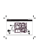
PCB 22. PCB layout.
Diagram 23.
01 SOLDERLESS EDUCATIVE STARTERBOX The EDU01 basic experiment kit is the first step into the world of modern electronics. Build your own circuits in a fun, safe and educative way. 02 SOLAR ENERGY EXPERIMENT KIT 04 Enter the world of microcontroller programming, easy step by step instructions. Includes programmer and test board. 05 Fun solar powered projects. Learn all about solar energy. 03 SOLDER EDUCATIVE STARTER BOX Learn how to solder, build different exciting projects.