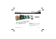
Total solder points: 202 Difficulty level: beginner 1 2 3 4 5 advanced DMX CONTROLLED POWER DIMMER K8039 ha mps troug ins la f o p u ro a lamp or g ve and m Control a Suitable for resisti Specifications al. g. DMX sign ge halogen lightin a control source: DMX-512, 3 pin XLR socket included lt vo load capacity: max.
VELLEMAN NV Legen Heirweg 33 9890 Gavere Belgium Europe www.velleman.be www.velleman-kit.
Features & specifications This kit allows you to control a lamp or group of lamps through a DMX signal. The DMX protocol was developed by USITT in 1986 with the purpose of controlling dimmers, scanners, moving heads and other lighting devices with simple wiring. It is mainly being used in theatres and discos, but you can use it in any place where a central or automated lighting is needed.
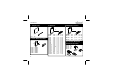
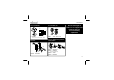
Assembly hints 1. Assembly (Skipping this can lead to troubles ! ) Ok, so we have your attention. These hints will help you to make this project successful. Read them carefully. 1.1 Make sure you have the right tools: • A good quality soldering iron (25-40W) with a small tip. • Wipe it often on a wet sponge or cloth, to keep it clean; then apply solder to the tip, to give it a wet look. This is called ‘thinning’ and will protect the tip, and enables you to make good connections.
Assembly hints 1.3 Soldering Hints : 1- Mount the component against the PCB surface and carefully solder the leads 2- Make sure the solder joints are cone-shaped and shiny 3- Trim excess leads as close as possible to the solder joint REMOVE THEM FROM THE TAPE ONE AT A TIME ! DO NOT BLINDLY FOLLOW THE ORDER OF THE COMPONENTS ONTO THE TAPE.
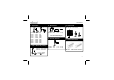
Construction 1. Jumper wires 4. Metal film resistors 3. Resistors R... J : 6x 2. Diodes. Watch the polarity ! CATHODE D1 : 1N4007 D2 : 1N4007 D3 : 1N4007 D4 : 1N4007 D5 : 1N4007 D6 : 1N4007 6 D... R1 R2 R3 R4 R5 R6 R7 R8 R9 R10 R11 R12 R13 R14 R15 R16 R17 R18 R19 : : : : : : : : : : : : : : : : : : : 10K 10K 10K 10K 10K 10K 10K 10K 10K 10K 10K 100K 1K5 1K5 1K5 1K5 2K2 1M 330 R...
Construction 6. Capacitors. 10. Pin header 8. 1W Resistor. c... C... R... JP2 : 2p (mode selection) 2m m C1 C2 C3 C4 C5 C6 C7 C8 C9 : : : : : : : : : 15pF 15pF 10nF 10nF 100nF 100nF 100nF 100nF 100nF R23 : 22K (15) (15) (103) (103) (104) (104) (104) (104) (104) Do not mount R24 yet ! 9. Vertical resistors 11. Piano DIP switch R... 7. LED’s. Watch the polarity ! COLOR= 2...
Construction 12. Capacitor. 15. Electrolytic capacitors Watch the polarity! C10 : 220µF/25V C11 : 220µF/25V C... 17. Fuses F... C12 : 100nF / 250Vac 13. Board to wire connector 16. Terminal blocks F1 : 5A (slow) F2 : 100mA (fast) 18. Voltage regulator SK4 : 3p DMX input VR... SK1 : 2p SK2 : 2p 14. Quartz crystal AC input Lamp output X...
Construction 19. Transformer 21. Toroidal coil L... 245V 230V 12V 115V 100V 0 Put an extra layer of solder on all copper PCB tracks to improve current handling capabilities 0 L1 : 1mH / 1kHz - 5A Transfo (2,5VA / 1x12V / 100V-115V-230V - 245V) 22. IC's. Watch the position of the notch 20.
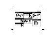
Choose operation voltage 23. Choose operation voltage 230V : R24 : 22K 230V (2 - 2 -3 - B) 2m m Mount a wire jumper for JP1 according to the figure 230 / 115 115V : 115V Mount for R24 a wire jumper Mount a jumper wire for JP1 according to the figure 230 / 115 10 CHECK THOROUGHLY ALL THE COMPONENTS FOR MISS MOUNTING, INCLUDING SOLDERING ERRORS.
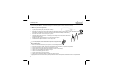
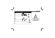
XLR plug 24. Wiring the 3P XLR plug Solder the 3-pole female print connector to the XLR connector using the figure below to check the accuracy of the connections (see figure 1.0) 1 (Brown) Legend : 2 (Red) 2 Red 1 Ground 2 Data - 3 (Orange) 3 Data + Orange 3 1 Brown Fig. 1.
Check-up 25. Check-up CAUTION: MOST PARTS OF THE CIRCUIT CARRY DANGEROUS VOLTAGES (MAINS) ! OBSERVE ALL SAFETY REQUIREMENTS THAT MIGHT APPLY ! MOUNT THIS KIT PREFERABLY IN AN ISOLATING HOUSING. Check the optical isolation between the mains voltage terminals (SK1 and SK2) and the DMX connecter terminals (SK4) by means of a multimeter (fig 2.0). Resistance should be infinite. 1 Ω Fig. 2.
Stand-alone test 26. Stand-alone test The K8039 consists of 2 internal parts: a low-voltage part taking care of the DMX decoding and a highvoltage part controlling the lamp. You can test the latter part with the self-testing function Make sure the PCB is not live! Close the “mode” jumper, JP2 by means of a shunt. Set the DMX address to 0, i.e. all switches to “OFF”. Connect a light bulb (min 60W) with the output (LAMP OUT).
Connection & use 27. Connection & use 1. Connect a lamp or lamp group with the “LAMP OUT” (SK2) output. Watch the output power: it should be between 60 and 1000W and shouldn’t be a capacitive (ex. electronic transformer) or an inductive charge (ex. halogen lighting with transformer). N L 2. Connect the DMX signal to the “DMX IN” input (SK4). 14 SK2 LAMP OUT Fig. 3.
Connection & use 3. Set up the DMX channel to which the K8039 has to react: Set up the DMX channel or “DMX address” by means of the DIPSWITCH, SW1. You can set up the DMX channel between 1 and 511, channel 0 is not used. The switches from 1 to 9 generate a binary digit representing the DMX channel. Switch 1 is the LSB, switch 9 is the MSB. Only modify the DMX channel when the K8039 is not live. Make sure to turn the kit live after every modification. 1 4 7 2 5 8 3 6 9 Fig. 4.
Connection & use 4. Switch 10 of the SW1 to ON when using the K8039 as sole connected DMX device or when it is the last connected device in the series. Connect the last fixture in the series with a “terminator resistor” of 120 ohm. The PCB is already equipped with a terminating resistance. Activate it as follows: switch 10 of the DIP switch to “ON”. Do not engage the terminating resistance on all the other fixtures in the series. In other words, set switch 10 to “OFF” on all other K8039 kits. 5.
DMx error correction 28. DMX error correction mode (JP2 “mode”) In normal mode (JP2 not mounted) the dimmer reacts every time, i.e. as fast as possible to the destined DMX value. In this mode it is possible to make fast yet fluid fading effects. When the error correction mode is enabled (JP2 mounted) the set luminosity will be more stable. It may be necessary with some brands of DMX equipment. Due to the high tolerance in the DMX protocol not all DMX controllers run stable together with the DMX fixtures.
PCB 29.
diagram 30.
Modifications and typographical errors reserved - © Velleman nv.