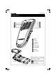
5 Channel IR transmitter ,4 receiver kits IR n a m e ll e ceivers in with most V f multiple re Compatible o e s u e th ow adresses all one room.
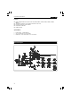
Features & specifications Features: Works together with K6711, K6712, K6713, K8046, K8050, K4100, K4500, MK161, MK163, MK164, … 4 addresses allow the use of multiple receivers in one room Ergonomic design for extra comfort. LED function indication. Rubber keypad Specifications: • • • Power supply : 3 AAA batteries Up to 15 channels can be operated. Dimensions : 150 x 58 x 22mm / 5,9 x 2,3 x 0,86” Schematic diagram.
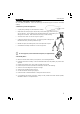
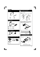
Assembly hints 1. Assembly (Skipping this can lead to troubles ! ) Ok, so we have your attention. These hints will help you to make this project successful. Read them carefully. 1.1 Make sure you have the right tools: • A good quality soldering iron (25-40W) with a small tip. • Wipe it often on a wet sponge or cloth, to keep it clean; then apply solder to the tip, to give it a wet look. This is called ‘thinning’and will protect the tip, and enables you to make good connections.
Assembly hints 1.
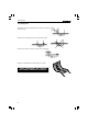
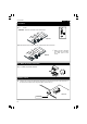
Construction 1. Jumpers 5. LEDs. Watch the polarity! LD2 : 3mm RED m First : Bend the leads exactly like the drawing. (Fig 1.0) 9m FIG. 1.0 m 9m J1 J2 J3 J4 J5 J6 2. 1/8W Resistors R... R1 R2 R3 R4 R5 : 100K : 100K : 10 : 470 : 470 Next : Mount this LED like in the drawing (fig. 2.0). Solder one lead, check the position, if necessary correct it by heating the soldering. Last solder the second connection. (1-0-4-B) (1-0-4-B) (1-0-0-B) (4-7-1-B) (4-7-1-B) 3. Ceramic Capacitor FIG. 2.
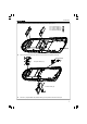
Construction 7. Transistor T1 : BC639 Attention : Mount the transistor on the solder side! T1 FIG. 5.0 Now bend the transistor towards the pcb, away from the IR & 3mm LED. FIG. 6.0 Make sure the transistor connections do not contact any other parts of the circuit. 8. IC. Watch the position of the notch! IC1 : VK8049 programmed Pic16F630. 9. Battery contacts Solder a wire of 7cm (Ø 0,20mm)to the negative (-) connection of the PCB.
Construction Now place the battery contacts into the housing on their right places. Positive battery lip Common battery lip Common battery lip Negative battery lip 4 3 1 2 3 4 2 1 FIG. 8.0 Connect now the wire that you earlier have mount to the negative battery lip. Negative battery lip Positive battery lip Connect a jumper between the positive battery lip and positive connection on the pcb.
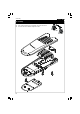
Assembly 10. Assembly First bend the battery lips over before closing the enclosure. Close the enclosure with the supplied screws. FIG. 9.
Keyboard layout 11. Keyboard Layout 2 1 4 3 6 5 8 7 SHIFT 1 Mute 2 Power 3 Volume up 3 Preset up 5 Volume down 6 Preset down 7 Source 8 Tuner seek Insert the batteries in the battery compartment as indicated in fig. 10 and close the compartment. FIG. 10 Remark : Respect your national and local laws when disposing of empty batteries.
Mode selection & Use 12. Mode selection At first power up, mode 1 is automatically selected. Press and hold SHIFT to change mode. Led starts flashing. Press button 1..8 to select desired mode as shown below. Hint : When the batteries are inserted, the led flashes 1..4 times indicating the selected mode. Key Description 1 'K6710 emulation with D4 mounted'- mode. Allows control of MK161/K8050/K6711/12/13. 15 channels available ('shift' & '8' = all clear). Shift is cleared after each key press.
PCB 14. PCB layout.
VELLEMAN KIT NV Legen Heirweg 33 9890 Gavere Belgium Europe Info ?: http://www.velleman.