Assembly instructions
Manuals
Brands
Velleman projects Manuals
Hardware
K8097
11
12
13
14
15
16
17
18
19
20
- 14 -
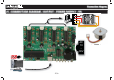
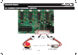
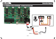
Connection diag
ram
22. CONNECTION DIA
GRAM : INPUTS
ex. alert switch
ex. limit switch
INPUT
IN
P
1
...
...
12
13
14
15
16
...
...
20