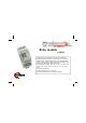
Relay module VMB1RY normal open & normal closed relay contacts: 5A/230VAC 10 different operation modes : moment control, on/off control, start/stop timer, staircase lighting timer, non-restartable timer, switch-off delay, switch-on delay, start timer by releasing push button, timer with blinking effect, 2-way timer 16 possible time settings : moment - 5s - 10s - 15s - 30s - 1min 2 min - 5min - 10min - 15min - 30min – 1h – 2h – 5h – 1day – on/off 247 possible addresses required power supply: 12 … 18VDC power
1 12 NC COM COM NO VMB1RY Relay module Out velleman BCDE 3 4 56 7 8 9A F0 1 2 7 8 9A BCDE 3 4 56 Mode/ ADDR.
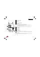
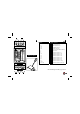
ENGLISH 6 13 VMB1RY Relay module BCDE BCDE 7 8 9A 7 8 9A BCDE F 0 12 12 3 456 3 456 7 8 9A Learn 3 456 F 0 12 Out ON F 0 12 7 8 9A F 0 12 3 456 BCDE Mode/ ADDR. Time2 14 1 2 3 4 5 6 7 Time1 11 9 Term Mode ON Rx Tx 7 10 8 15 8 9 10 11 12 13 14 15 Normal closed contact Normal open contact 12V supply Velbus Direct push button control Relay-on indication LED Mode-LED : The LED will not light if the relay is switched of.
13 Operation mode (page 2&3) The relay module will operate as follows, depending on the setting of the 'MODE/TIME2' rotary switch (see ‘TIME1’ rotary switch): 0 Start/stop timer : Operating the push button will switch on the relay. After the set time has elapsed, the relay turns off. Operating the push button when the relay is switched on will immediately switch off the relay. 1 Staircase lighting timer : Operating the push button will switch on the relay.
Learning mode: Only push buttons connected to the Velbus® via a push button interface or a control panel are appropriate for the procedure below. Each command can accept up to 7 different push buttons. Memorize he unique address of the module.
2 1 12 NC COM COM NO VMB1RY Relay module 3 4 56 BCDE BCDE 3 4 56 7 8 9A F0 1 2 7 8 9A F 0 12 02 F 1 F1 : OFF E1 : ON D1 : TGL C1 : PBM 3 4 56 F 102 Learn 7 8 9A BCDE BCDE 3 4 56 Time1 7 8 9A B1 : TG1 A1 : TG2 91 : ST1 81 : ST2 ON - 12V+ SUPPLY Rx Mode/ Time1 Time2 0:Mom Strt-stp 1:5s Staircs 2:10s NoRtrg 3:15s Off Dly 4:30s On Dly Trg Rel 5:1' 6:2' Blink 7:5' 5' 8:10' 10' 9:15' 15' A:30' 30' B:1h 1h C:2h 2h D:5h 5h E:1day 1day F:Tgl Tgl Tx L H TIME 1 Out velleman Mode/ ADDR.
NEDERLANDS 6 13 VMB1RY Relay module BCDE BCDE 7 8 9A 7 8 9A BCDE F 0 12 12 3 456 3 456 7 8 9A Learn 3 456 F 0 12 Out ON F 0 12 7 8 9A F 0 12 3 456 BCDE Mode/ ADDR. Time2 14 1 2 3 4 5 6 7 Time1 11 9 Term Mode ON Rx Tx 7 10 8 15 8 9 10 11 12 13 14 15 Normaal gesloten contact Normaal open contact 12V voeding Velbus Directe drukknopbediening Relais aan indicatie-LED Mode-LED : De LED brandt niet indien het relais uitgeschakeld is.
13 Werkingsmode (zie bladzijde 6&7) Afhankelijk van de instelling van deze 'MODE/TIME2' draaischakelaar zal de relaismodule als volgt functioneren (zie ‘TIME1’draaischakelaar): 0 Start/stop timer : Bedienen van de drukknop schakelt het relais in. Nadat de ingestelde tijd verlopen is, schakelt het relais uit. Bedienen van de drukknop wanneer het relais aan is, zal het relais onmiddellijk uitschakelen. 1 Trappenhuisautomaat : Bedienen van de drukknop schakelt het relais in.
Leermode: Enkel drukknoppen die via een drukknopinterface of bedieningspaneel op de VELBUS aangesloten zijn komen in aanmerking voor onderstaande procedure. Er kunnen tot 7 verschillende drukknoppen aangeleerd worden per bedieningsfunctie. Onthoud het unieke adres van de module.
2 1 NC COM COM NO VMB1RY Relay module Out velleman BCDE 3 4 56 7 8 9A F0 1 2 7 8 9A BCDE 3 4 56 Mode/ ADDR.
FRANCAIS 6 13 VMB1RY Relay module BCDE BCDE 7 8 9A 7 8 9A BCDE 12 3 456 3 456 7 8 9A Learn F 0 12 Time1 11 9 Term Mode ON Rx Tx 7 10 8 15 Contact normal fermé Contact normal ouvert Alimentation 12V Velbus Contrôle direct des boutons poussoirs Voyant LED relais enclenché LED de mode d’opération La LED ne s’allume pas si le relais est coupé. La LED s’allume si le relais est enclenché et le minuteur n’est pas activé. La LED clignote rapidement si le minuteur est activé.
13 Mode d’opération (page 10&11) En fonction du réglage de cet interrupteur rotatif 'MODE/TIME2' le module relais fonctionnera de la manière suivante (voir 'TIME1'): 0 1 2 3 4 5 6 7-F Minuteur marche/arrêt : L’actionnement du bouton poussoir enclenchera le relais. Le relais se coupe après l’écoulement du délai introduit. L’actionnement du bouton poussoir lorsque le relais est enclenché, coupera le relais instantanément.
Mode d’apprentissage: La procédure décrite ci-dessous n’est applicable que pour les boutons-poussoirs connectés au Velbus® via une interface de boutonpoussoir ou un panneau de commande. Il est possible d’apprendre jusqu’à 7 différents boutons poussoirs par fonction de commande : Mémorisez l’adresse du module.
2 1 NC COM COM NO VMB1RY Relay module Out velleman BCDE 3 4 56 7 8 9A F0 1 2 7 8 9A BCDE 3 4 56 Mode/ ADDR.
DEUTSCH 6 13 VMB1RY Relay module BCDE BCDE 7 8 9A 7 8 9A BCDE F 0 12 12 3 456 3 456 7 8 9A Learn 3 456 F 0 12 Out ON F 0 12 7 8 9A F 0 12 3 456 BCDE Mode/ ADDR. Time2 14 1 2 3 4 5 6 7 Time1 11 9 Term Mode ON Rx Tx 7 10 8 8 9 10 11 12 13 14 15 15 normal geschlossen"-Kontakt normal "offen"-Kontakt 12V-Stromversorgung Velbus direkte Drucktastenbedienung Relais –ein-Anzeige Betriebsmodus-LED Die LED brennt nicht wenn das Relais ausgeschaltet ist.
13 Betriebsmodus (Seite 14&15) Abhängig von der Einstellung dieses 'MODE/TIME' Drehschalters wird das Relaismodul wie folgt funktionieren (siehe 'TIME1') : 0 1 2 3 4 5 6 7-F Start/Stop-Timer : Eine Bedienung der Drucktaste schaltet das Relais ein. Nachdem die eingestellte Zeit verstrichen ist, schaltet das Relais aus. Eine Bedienung der Drucktaste wenn das Relais schon eingeschaltet ist, wird das Relais sofort ausschalten. Treppenhausautomat : Eine Bedienung der Drucktaste schaltet das Relais ein.
Lernmodus: Nur Drucktasten, die über eine Drucktastenschnittstelle oder ein Bedienfeld mit dem Velbus®-System verbunden sind, eignen sich für das Verfahren (siehe unten). Es können bis zu 7 verschiedene Drucktasten programmiert werden. Speichern Sie die einzigartige Adresse des Moduls.
2 1 NC COM COM NO VMB1RY Relay module Out velleman BCDE 3 4 56 7 8 9A F0 1 2 7 8 9A BCDE 3 4 56 Mode/ ADDR.
ESPAÑOL 6 13 VMB1RY Relay module BCDE BCDE 7 8 9A 7 8 9A BCDE F 0 12 12 3 456 3 456 7 8 9A Learn 3 456 F 0 12 Out ON F 0 12 7 8 9A F 0 12 3 456 BCDE Mode/ ADDR. Time2 14 1 2 3 4 5 6 7 Time1 11 9 Term Mode ON Rx Tx 7 10 8 15 8 9 10 11 12 13 14 15 Contacto normalmente cerrado Contacto normalmente abierto Alimentación 12V Velbus Control directo de los pulsadores Indicador LED relé activado LED de modo de funcionamiento El LED no se ilumina si el relé está desactivado.
13 Modo de funcionamiento (pág. 18&19) The relay module will operate as follows, depending on the setting of the 'MODE/TIME2' rotary switch (Véase 'TIME1'): 0 1 2 3 4 5 6 7F Temporizador start/stop : Si se pulsa el pulsador el relé se activará. El relé se desactivará después de que el tiempo introducido haya transcurrido. Si se pulsa el pulsador mientras el relé está activado, este se desactivará inmediatamente. Temporizador de caja de escalera : Si se pulsa el pulsador el relé se activará.
Modo de aprendizaje: El procedimiento descrito a continuación sólo es apto para pulsadores conectados al Velbus® por una interfaz de pulsadores o un panel de control. Es posible programar hasta 7 diferentes pulsadores por función de control: Memorice la dirección del módulo.
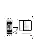
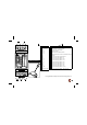
Control via push buttons and/or VELBUS system: Besturing door drukknoppen en/of velbusbediening Contrôle à partir de plusieurs boutons poussoirs et/ou système VELBUS Steuerung über Drucktasten und/oder VELBUS-System control por varios pulsadores y/o el sistema VELBUS Direct control with several push buttons: Directe bediening met meerdere drukknoppen Contrôle direct avec plusieurs boutons poussoirs Direkte Bedienung mit mehreren Drucktasten Control directo con varios pulsadores N N AC POWER AC POWER L
2-pole interruption / 4-pole interruption 2-polige onderbreking / 4-polige onderbreking Interruption à double pôle / interruption à 4 pôles 2-pol. Unterbrechung / 4-pol.
VELLEMAN Components NV Legen Heirweg 33 9890 Gavere Belgium Europe www.velleman.be www.velleman-kit.com www.velbus.be Modifications and typographical errors reserved - © Velleman Components nv.