
user manual Owner manual


3
1
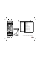
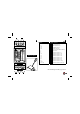
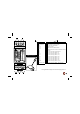
Normal closed contact
2
Normal open contact
3
12V supply
4
Velbus
5
Direct push button control
6
Relay-on indication LED
7
Mode-LED :
The LED will not light if the relay is switched of.
The LED lights if the relay is witched on and the timer is not activated.
The LED blinks rapidly if the timer is activated.
The LED blinks slowly if the 2
nd
timer is activated in the 2-way timer mode.
The LED blinks fast if the module is activated in the ‘learning’ mode.
8
Forwarding LED
9
Power LED
10
Reception LED
11
Manual control
12
Time setting
13
Control mode setting
14
Adress setting
Enter a unique address (from ‘00’ to ‘FE’ except for ‘81’, ‘91’, ‘A1’, ‘B1’, ‘C1’,
‘D1’, ‘E1’, ‘F1’ and ‘FF’) for each module through the ‘ADDR’ rotating switches
15
Termination
If the module is connected at the start or end of a cable on the VELBUS, place the
‘TERM’ jumper. Remove the jumper in all other cases.
VMB1RY
Out
Relay module
Learn
ON
Mode
Tx
Rx
ADDR.
Time1
Mode/
Time2
A
9
8
7
6
5
4
3
2
1
0
F
E
D
C
B
A
9
8
7
6
5
4
3
2
1
0
F
E
D
C
B
A
9
8
7
6
5
4
3
2
1
0
F
E
D
C
B
A
9
8
7
6
5
4
3
2
1
0
F
E
D
C
B
Term
Out
ON
14
6
13
12
9
10
8
15
7
11
ENGLISH