
Assembly Manual

START
5
CAPACITOR
c...
DIODES
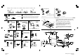
SCHEMATIC DIAGRAM
1
R...
◊ R1…R3 : 560
◊ R4, R5 : 47K
Resistor - Weerstand -
Résistance - Widerstand -
Resistencia - Motstand -
Vastus - Resistenze
(Yellow, Purple, Orange) -(Geel, Paars, Oranje) -(Jaune, Violet, Orange) -(Gelb,
Violet, Orange) -(Gul, Lila, Orange) -(Keltainen, Purppura, Oranssi) - (Amarillo,
Morado, Naranjado) -(Amarelo, Violeta, Laranja) - (Giallo, Viola, Aranciato)
2
◊ C2, C3 : 100nF (104)
IR-RECEIVER
7
Soldering - Solderen - Soudage - Löten - Soldadura - Lödning - Juottami nen - Saldatura - Solda
3
max.
40W
1
2
(Green, Blue, Brown) -(Groen, Blauw, Bruin) -(Vert, Bleu, Brun) -(Grün, Blau,
Braun) - (Grön, Blå, Brun) -(Vihreä, Sininen, Ruskea) -(Marrón, Azul, Marrón) -
(Verde, Azul, Castanho) -(Verde, Blu, Marrone)
D...
CATHODE
◊ D1 : 1N4007
◊ D2 , D3 : 1N4148
Watch the polarity!
Att. À la polarité!
IC SOCKET
WATCH THE POSITION
OF THE NOTCH !
ATTENTION A LA POSITION
DE L’EN-
◊ IC1 : 8p
3
4
Watch the
polarity !
Attention à la
polarité !
LED’s
6
PUSH BUTTON
◊ SW1 : Prog.
SW...
GND
+V
OUT
◊ IRx1 : MS-M638VM
9
◊ T1, T2 : BC547
VR...
VOLTAGE
REGULATOR
◊ VR1 : UA78L05
ELECTROLYTIC
CAPACITORS
11
Watch the polarity!
Att. À la polarité!
◊ C1 : 100µF
12
RELAYS
◊ RY1, RY2 : VR3D121C6
13
SCREW CONNECTORS
K
3
S
K
2
S
K
1
R...
(Yellow, Purple, Orange) - (Geel,
Paars, Oranje) -( Jaune, Violet,
Orange) -(Gelb, Violet, Orange)
RESISITORS
◊ R6, R7 (47K)
8
TRANSISTORS
◊ SK1 : 12VDC
◊ SK2 : output 1 (NO- contact)
◊ SK3 : output 2 (NO- contact)
10
GP4/OSC2
3
V
d
d
1
GP5/OSC1/CLKIN
2
GP3/MCLR/Vpp
4
GP2/T0CKl
5
GP0
7
GP1
6
V
s
s
8
IC1
PIC12F629
R1
5
60
R5
47K
R4
47K
R
3
5
60
R2
5
60
T
1
B
C547
T
2
B
C547
L
D3
L
ED3RL
L
D2
L
ED3RL
L
D1
LED3RL
SW1
SW KRS0611
SK1
12VDC
D
3
1
N4148
D2
1N4148
D
1
1N4007
G
ND
G
ND
C3
100n
GND
C1
100µ
GND
GND
GND
+5V
+
V
OUT
G
N
D
IRx1
I
R
-
R
E
C
E
I
V
E
R
M
S
-
M
6
3
8
V
M
+5V
GND
+5V
+
12V
+5V
GND
G
ND
RY1
R
Y2
SK2
SK3
+
12V
+12V
I
O
G
N
D
V
R1
UA78L05
GND
C2
100n
GND
R
7
4
7K
R
6
4
7K
Output 2
Output 1
12VDC
LD3
(Out 2)
LD2
(Out 2)
Rx LD1
◊ To choose between ‘PULSE’ and ‘TOGGLE’ : press and hold the
‘PROG’-button and press the button of the desired channel on the
remote.
LD1 : one flash = ‘PULSE’ , two flashes = ‘TOGGLE’.
◊ To change the button to which the receiver responds,
press the ‘PROG’-button until the desired channel is
turned on. Next, press the remote button to which you
would like the receiver to respond.
◊ To return to factory settings, press and hold the ‘PROG’-
button while applying power to the unit. LD1 will flash 5
times.
INSTRUCTIONS
13
IC
14
◊ IC1 : PIC12F629
LD...
CATHODE
CATHODE
8
m
m
8
m
m
◊ LD1 … LD3 : Red / Rood / Rouge / Rot / Röd /
Punainen / Rojo / Encarnado / Rosso
◊ SK1, SK2, SK3 : 2p
MK161.pub
page 1
Thursday, June 12, 2003 11:08
Composite