
Data Sheet


MFRC522 All information provided in this document is subject to legal disclaimers. © NXP Semiconductors N.V. 2016. All rights reserved.
Product data sheet
COMPANY PUBLIC
Rev. 3.9 — 27 April 2016
112139 57 of 95
NXP Semiconductors
MFRC522
Standard performance MIFARE and NTAG frontend
9.3.3 Page 2: Configuration
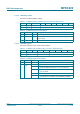
9.3.3.1 Reserved register 20h
Functionality is reserved for future use.
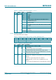
9.3.3.2 CRCResultReg registers
Shows the MSB and LSB values of the CRC calculation.
Remark: The CRC is split into two 8-bit registers.
Table 85. Reserved register (address 20h); reset value: 00h bit allocation
Bit 7 6 5 4 3 2 1 0
Symbol -
Access reserved
Table 86. Reserved register bit descriptions
Bit Symbol Description
7 to 0 reserved reserved for future use
Table 87. CRCResultReg (higher bits) register (address 21h); reset value: FFh bit allocation
Bit 7 6 5 4 3 2 1 0
Symbol CRCResultMSB[7:0]
Access R
Table 88. CRCResultReg register higher bit descriptions
Bit Symbol Description
7 to 0 CRCResultMSB
[7:0]
shows the value of the CRCResultReg register’s most significant
byte
only valid if Status1Reg register’s CRCReady bit is set to logic 1
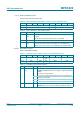
Table 89. CRCResultReg (lower bits) register (address 22h); reset value: FFh bit allocation
Bit 7 6 5 4 3 2 1 0
Symbol CRCResultLSB[7:0]
Access R
Table 90. CRCResultReg register lower bit descriptions
Bit Symbol Description
7 to 0 CRCResultLSB
[7:0]
shows the value of the least significant byte of the CRCResultReg
register
only valid if Status1Reg register’s CRCReady bit is set to logic 1