VMA501 DIY STARTER KIT FOR ARDUINO ® USER MANUAL
VMA501 USER MANUAL 1. Introduction To all residents of the European Union Important environmental information about this product This symbol on the device or the package indicates that disposal of the device after its lifecycle could harm the environment. Do not dispose of the unit (or batteries) as unsorted municipal waste; it should be taken to a specialized company for recycling. This device should be returned to your distributor or to a local recycling service. Respect the local environmental rules.
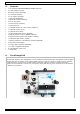
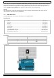
VMA501 5. Contents 1 x ATmega328 UNO DEVELOPMENT BOARD (VMA100) 15 x LED (different colors) 8 x 220 Ω resistor (RA220E0) 5 x 1k resistor (RA1K0) 5 x 10k resistor (RA10K0) 1 x 830 hole breadboard 1 x RGB LED module (VMA318) 4 x 4-pin Key switch 1 x active buzzer (VMA319) 1 x passive buzzer 1 x 1838 IR infrared 37.
VMA501 1 USB interface 6 16 MHz clock 2 reset button 7 Atmel mega328p (DIL) 3 digital I/O 8 7-12 VDC power input 4 Atmel mega16U2 9 power and ground pins 5 ICSP 10 analogue input pins microcontroller .................................................................................................. ATmega328 operating voltage ....................................................................................................... 5 VDC input voltage (recommended) ...........................
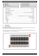
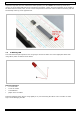
VMA501 Chips have legs that come out of both sides and fit perfectly over the ravine. Since each leg on the IC is unique, we do not want both sides to be connected to each other. That is where the separation in the middle of the board comes in handy. Thus, we can connect components to each side of the IC without interfering with the functionality of the leg on the opposite side. Ravine. 7.2 A Blinking LED Let’s start with a simple experiment.
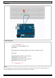
VMA501 Connection Programming Code Result After programming, you will see the LED connected to pin 10 blinking, with an interval of approximately one second. Congratulations, the experiment is now successfully completed! V.
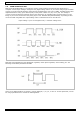
VMA501 7.3 PWM Gradational LED PWM (Pulse Width Modulation) is a technique used to encode analogue signal levels into digital ones. A computer cannot output analogue voltage but only digital voltage values. So, we will be using a high-resolution counter to encode a specific analogue signal level by modulating the duty cycle of PWM. The PWM signal is also digitalized because in any given moment, fully on DC power is either 5 V (on) of 0 V (off).
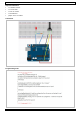
VMA501 Required Hardware 1 x variable resistor 1 x red M5 LED 1 x 220 Ω resistor 1 x breadboard jumper wires as needed Connection Programming Code V.
VMA501 In this code, we are using the analogWrite (PWM interface, analogue value) function. We will read the analogue value of the potentiometer and assign the value to PWM port, so there will be corresponding change to the brightness of the LED. One final part will be displaying the analogue value on the screen. You can consider this as the analogue value reading project adding the PWM analogue value assigning part.
VMA501 Programming Code V.
VMA501 7.5 The Active Buzzer An active buzzer is widely used on computers, printers, alarms, etc. as a sound-making element. It has an inner vibration source. Simply connect it with a 5 V power supply to make it buzz constantly. Required Hardware 1 x buzzer 1 x key 1 x breadboard jumper wires as needed V.
VMA501 Connection Programming Code Result After programming, the buzzer should ring. V.
VMA501 7.6 The Photosensitive Resistor A photoresistor is a resistor whose resistance varies according to different light strengths. It is based on the photoelectric effect of a semiconductor. If the incident light is intense, the resistance reduces; if the incident light is weak, the resistant increases. A photovaristor is commonly applied in the measurement of light, light control and photovoltaic conversion. Let’s start with a relative simple experiment.
VMA501 Programming Code Result After programming, change the light strength around the photovaristor and observe the LED changing! 7.7 The Flame Sensor A flame sensor (IR receiving diode) is specifically used on robots to find the fire source. This sensor is highly sensitive to flames. A flame sensor has a specifically designed IR tube to detect fire. The brightness of the flames will then be converted to a fluctuating level signal. The signals are the input into the central processor.
VMA501 Connection Connect the negative to the 5 V pin and the positive to the resistor. Connect the other end of the resistor to GND. Connect one end of a jumper wire to a clip, which is electrically connected to sensor positive, the other end to the analogue pin. Programming Code V.
VMA501 7.8 The LM35 Temperature Sensor The LM35 is a common and easy-to-use temperature sensor. It does not require other hardware, you just need an analogue port to make it work. The difficulty lies in compiling the code to convert the analogue value it reads to Celsius temperature. Required Hardware 1 x LM35 sensor 1 x breadboard jumper wires as needed Connection V.
VMA501 Programming Code Result After programming, open the monitoring window to see the current temperature. 7.9 The Tilt Sensor Switch A tilt sensor will detect orientation and inclination. They are small, low power and easy-to-use. If used properly, they will not wear out. Their simplicity makes them popular for toys, gadgets and other appliances. They are referred to as mercury, tilt or rolling ball switches.
VMA501 Programming Code V.
VMA501 7.10 The IR Receiver Infrared communication is a common, inexpensive and easy-to-use wireless communication technology. IR light is very similar to visible light, except that it has a slightly longer wavelength. This means that IR is undetectable to the human eye – perfect for wireless communication. Example: When you hit a button on your TV remote, an IR LED repeatedly turns on and off, 38000 times a second, to transmit information to an IR photo sensor on your TV. Connection V.
VMA501 Programming Code 7.11 One-Digit Seven-Segment Display LED segment displays are common for displaying numerical information. They are widely applied on displays of ovens, washing machines, etc. the LED segment display is a semiconductor light-emitting device. Its basic unit is an LED (light-emitting diode). Segment displays can be divided into 7-segment and 8-segment displays.
VMA501 For the common anode display, connect the common anode (COM) to +5 V. When the cathode level of a certain segment is low, the segment is on; when the cathode level of a certain segment is high, the segment is off. For the common cathode display, connect the common cathode (COM) to GND. When the anode level of a certain segment is high, the segment is on; when the anode level of a certain segment is low, the segment is off. Connection Programming Code V.
VMA501 7.12 Four-Digit Seven-Segment Display V.
VMA501 Connection Programming Code This is an example of how to drive a 7-segment LED display without the use of current limiting resistors. This technique is very common but requires some knowledge of electronics – you do run the risk of dumping too much current through the segments and burning out parts of the display. If you use the stock code you should be ok, but be careful editing the brightness values.
VMA501 V.
VMA501 V.
VMA501 V.
VMA501 V.
VMA501 V.
VMA501 7.13 8x8 LED Matrix With low-voltage scanning, LED dot-matrix displays have advantages such as power saving, long service life, low cost, high brightness, wide angle of view, long visual range, being waterproof… LED dot-matrix displays can meet the needs of different applications and thus have a broad development prospect. The 8*8 dot-matrix is made up of sixty-four LEDs, and each LED is placed at the cross point of a row and a column.
VMA501 Programming Code Use this device with original accessories only. Velleman nv cannot be held responsible in the event of damage or injury resulting from (incorrect) use of this device. For more info concerning this product and the latest version of this manual, please visit our website www.velleman.eu. The information in this manual is subject to change without prior notice. © COPYRIGHT NOTICE The copyright to this manual is owned by Velleman nv. All worldwide rights reserved.
Velleman® Service and Quality Warranty Since its foundation in 1972, Velleman® acquired extensive experience in the electronics world and currently distributes its products in over 85 countries. All our products fulfil strict quality requirements and legal stipulations in the EU. In order to ensure the quality, our products regularly go through an extra quality check, both by an internal quality department and by specialized external organisations.