DVM 890L LCD Standard Digital Multimeter LCD Standaard Digitale Multimeter Multimètre Digital LCD Standard USER MANUAL GEBRUIKERSHANDLEIDING MANUEL D’UTILISATION
DVM 890L LCD Standard Digital Multimeter 1. Introduction This instrument is a compact, rugged, battery-operated hand-held 3 1/2 digit digital multimeter for measuring DC and AC voltages, DC and AC current and resistance. It also offers the possibility of executing continuity tests and of testing diodes and transistors. You can also measure capacitance and temperatures. The Dual-Slope A/D Converter uses C-MOS technology for auto-zeroing, polarity selection and overrange indication.
2.
2.1 Function and range selector Various functions and 32 ranges are provided. A rotary switch is used to select functions as well as ranges. 2.2 Power switch A push-button is used to turn the meter on or off. To extend battery life, an Auto Power-Off function is provided. The meter will be turned off automatically within approx. 15 minutes. To turn the meter on again, push the power switch to release the Auto Power-Off function and then push it again. 2.
3. Operating instructions 1) Check the 9V battery by setting the ON-OFF switch to the ON position. If the battery is weak, a " " sign will appear on the display. If this sign does not appear on the display, proceed as mentioned below. Read MAINTENANCE if the battery has to be replaced. sign next to the test lead jacks warns you of the fact that the input voltage or current 2) The should not exceed the indicated values. This serves to prevent the internal circuitry from damage.
3.3 DC Current measurement 1) Connect the black test lead (-) to the COM input connector and the red test lead (+) to the mA input connector or a maximum of 200mA. Move the red test lead to the 20A MAX input connector for a maximum of 20A. 2) Set the FUNCTION switch to the A range. 3) Connect the test leads IN SERIES to the load under measurement. 4) Read LCD display. The polarity at the RED test lead connection will be indicated.
Note : 1) The overrange indication ("1") will be displayed if the resistance value being measured exceeds the maximum value of the selected range. Consequently, you should select a higher range. It may take the meter a few seconds to become stable when measuring a resistance of approximately 1 MΩ and more. This is normal for high resistance readings. 2) When the input is not connected, i.e. when the circuit is open, the figure " 1 " will be displayed for the overrange condition.
3.7 Diode measurement and Continuity test 1) Connect the black lead (-) to the COM input connector and the red lead (+) to the V/Ω/f input connector. 2) Set the FUNCTION switch to the / range and connect the test leads to the diode under measurement. The display will show the approx. forward voltage of this diode. 3) For continuity tests : connect the test leads to two random points of the circuit. A buzzer will sound if the resistance is lower than approx. 30Ω. 3.
4. Specifications Maximum accuracy is achieved during a one-year period after calibration. Ideal circumstances require a temperature of 23°C (± 5°C) and a relative humidity under 75%. 4.1 General Maximum display Indication method Measuring method Overrange indication Maximum common mode voltage Reading rate Temperature for guaranteed accuracy Temperature range Power supply Battery-low indication Size Weight Accessories 1999 counts (3 1/2 digits) with automatic polarity indication and eng. unit.
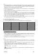
4.3 AC Voltage Range Resolution Accuracy 200mV 100µV ± 1.2% of rdg ± 3 digits 2V 1mV 20V 10mV ± 0.8% of rdg ± 3 digits 200V 100mV 700V 1V ± 1.2% of rdg ± 3 digits Input impedance : 10MΩ for all ranges Frequency range : 40 to 400Hz Overload protection : 750Vrms or 1000V peak continuous for the ac ranges, with the exception of the 200mV AC range (max.15 seconds above 300Vrms) 4.4 DC Current Range Resolution Accuracy 2mA 1µA ± 0.8% of rdg ± 1 digits 20mA 10µA 200mA 100µA ± 1.
4.6 Resistance Range 200Ω 2kΩ 20kΩ 200kΩ 2MΩ 20MΩ 200MΩ Resolution 0.1Ω 1Ω 10Ω 100Ω 1kΩ 10kΩ 100kΩ Accuracy ± 0.8% of rdg ± 3 digits ± 0.8% of rdg ± 1 digits ± 1% of rdg ± 2 digits ± 5% of rdg ± 10 digits For the 200MΩ range, short the two test leads first. If the displayed value comprises 10 digits, these 10 digits should be subtracted from the measurement result. 4.7 Capacitance Range 2000pF 20nF 200nF 2µF 20µF Resolution 1pF 10pF 100pF 1nF 10nF Accuracy ± 2.5% of rdg ± 5 digits 4.
4.10 Diode Test and Audible Continuity Test Range / / Description Display shows approx. forward voltage of diode Built-in buzzer sounds if conductance is less than approx. 30Ω Test Condition Forward DC current approx. 1mA Reversed DC voltage approx. 2.8 Volts Open circuit voltage approx. 2.8 Volts 5. Maintenance Your Digital Multimeter is an electronic precision instrument. In order to avoid damage, avoid tampering with the circuitry.