H.264 Network DVR User Manual GUI Display with USB Mouse Control Please read instructions thoroughly before operation and retain it for future reference. For the actual display & operation, please refer to your DVR in hand. 中文_k679b_677b_674b_c551b_m759b_757b_751b_688b_686b_a791b_Manual_V1.
IMPORTANT SAFEGUARD CAUTION RISK OF ELECTRIC SHOCK CAUTION: To reduce the risk of electric shock, do not expose this apparatus to rain or moisture. Only operate this apparatus from the type of power source indicated on the label. The company shall not be liable for any damages arising out of any improper use, even if we have been advised of the possibility of such damages.
Grounding This is a Safety Class 1 Product (provided with a protective earthing ground incorporated in the power cord). The mains plug shall only be inserted in a socket outlet provided with a protective earth contact. Any interruption of the protective conductor inside or outside of the instrument is likely to make the instrument dangerous. Intentional interruption is prohibited.
TABLE OF CONTENTS 1. BEFORE USING THIS DVR ......................................................................... 1 1.1 Package Content ......................................................................................................... 1 1.2 Front Panel .................................................................................................................. 1 1.3 Rear Panel ...................................................................................................................
.3.3 Alarm Timer ....................................................................................................... 21 5.4 Detection Setting ........................................................................................................ 22 5.5 PTZ Camera Setting .................................................................................................. 23 5.6 System Setting ........................................................................................................... 24 5.
BEFORE USING THIS DVR 1. BEFORE USING THIS DVR 1.1 Package Content ¾ ¾ Standard Package DVR HDD screws Adapter & Power cord CD Manual Optional Accessories IR Remote Controller USB Mouse Manual for IR Remote Controller DSUB Connector IR Receiver Extension Cable 1.2 Front Panel 1) LED Indicators HDD is reading or recording. An alarm is triggered. Timer recording is on. Under playback status. DVR is powered on.
BEFORE USING THIS DVR 7) SLOW In the playback mode, press to show slow playback. 8) ZOOM Press to enlarge the picture of selected channel in the FRAME or FIELD recording mode. 9) SEQ Press to display each channel in full screen one by one starting from CH1. When the last channel is displayed, it will repeat from CH1 again. To exit this mode, press “SEQ” again. 10) Press to show the 4-channel display mode. 11) CH1 ~ 16 / 1 ~ 8 / 1 ~ 4 Press the channel number keys to select the channel to display.
BEFORE USING THIS DVR function, please switch to 75Ω. 2) VIDEO IN (1 ~ 16 / 1 ~ 8 / 1 ~ 4): Connect to the video connector of a camera. VIDEO LOOP (1 ~ 16 / 1 ~ 8): Video output connector. (For Selected Models Only) Note: The DVR will automatically detect the video system of the camera, please make sure that the cameras are properly connected to the DVR and power-supplied before the DVR is turned on. 3) AUDIO IN (1 ~ 4) Connect to the audio connector of a camera if the camera supports audio recording.
CONNECTION AND SETUP 2. CONNECTION AND SETUP Before the DVR is powered on, make sure you have installed a hard disk and connected at least one camera. For details, please refer to the following sections. Note: The DVR is designed to automatically detect the video system of the connected cameras (NTSC or PAL). To make sure the system detection is correct, please check if the cameras are connected to the DVR and power-supplied before the DVR is powered on. 2.
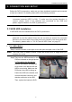
CONNECTION AND SETUP 2-2 To install on the second bracket Connect the power connector and data bus connector to the HDD. When connecting the power cable, make sure the cable is passed through the power cable of DVD writer if your DVR is equipped with a DVD writer. This is to prevent the HDD power cable from interfering with the fan spinning. Align the screw holes of the bracket with the HDD’s screw holes. Make sure the PCB side of the HDD is facing up. Then, fasten the HDD to the bracket.
CONNECTION AND SETUP Step4: Align the screw hole on the each bracket with the screw hole on the each side of the HDD as shown below, and fix the HDD to the bracket with a HDD screw supplied. Step5: Close the upper cover of the DVR, and fasten all the screws you loosened in Step 1. 2.2 Camera Connection The cameras must be connected and power-supplied before the DVR is powered on. Connect the camera with the indicated power supply.
CONNECTION AND SETUP 3) Connecting to power Connect the camera with indicated power supply and make sure it’s power-supplied. 2.2.2 PTZ Camera Connection (For Selected Models Only) The following description is taking our brand’s PTZ camera as an example. For DVR setting to control the PTZ camera, please refer to “5.5 PTZ Camera Setting” at page 23. For detailed PTZ camera control and operation, please refer to its own user manual.
CONNECTION AND SETUP For DVR PIN configuration, please refer to “APPENDIX 6 PIN CONFIGURATION” at page 61. For connection details, please check with your installer. STEP 5: Set the speed dome camera at the DVR side. Go to “ADVANCED CONFIG” l “DEVICES” to set the speed dome camera. a) Select the device to “PTZ”. b) Set the ID to the value the same as the one set in the speed dome camera. The default ID of the camera is 000. c) Select the protocol to “NORMAL”.
CONNECTION AND SETUP 2.4 Date and Time Setting Before operating your DVR, please set the date and time on your DVR FIRST. Note: Please DO NOT change the date or time of your DVR after the recording function is activated. Otherwise, the recorded data will be disordered and you will not be able to find the recorded file to backup by time search. If users change the date or time accidentally when the recording function is activated, it’s recommended to clear all HDD data, and start recording again.
CONNECTION AND SETUP SYSTEM TOOLS SYSTEM INFO BACKUP DATA (USB) BACKUP LOG (USB) BAUD RATE HOST ID R.E.T.R (For Selected Models Only) AUTO KEY LOCK CLEAR HDD RESET DEFAULT REMOTE CONTROL ID 2400 000 5 NEVER HDD-0 SUBMIT 000 SERIAL TYPE RS485 VIDEO FORMAT NTSC VERSION 1025-1011-1011-1012 EXIT 2.6 Password Setting Right-click to show the main menu, and select “SYSTEM” Æ “TOOLS” to change the DVR password. There are two user levels: ADMIN & OPERATOR. For details, please refer to “4.
GUI DISPLAY WITH USB MOUSE CONTROL 3. GUI DISPLAY WITH USB MOUSE CONTROL 3.1 Connect USB Mouse Connect your USB mouse to one of the USB ports on the DVR front panel, and check if ) on the screen, indicating the USB mouse is detected properly. there’s a mouse icon ( Move your mouse to enter the DVR password with the password keypad. The default administrator password is 0000. The status will be changed from (key lock) to (administrator), and the quick menu bar appears on the left side of the screen.
GUI DISPLAY WITH USB MOUSE CONTROL Click to select the audio channel you want: In the live mode, only the live audio channels can be selected. In the playback mode, live and playback audio channels can be selected. Click to enter the PTZ mode and show the PTZ camera control panel. For details, please refer to “3.2.2 PTZ Control Panel” at page 12. Click to show the power off panel to either halt or reboot the system. 3.2.
GUI DISPLAY WITH USB MOUSE CONTROL / / / Camera Menu Click to enter the camera main menu. For details about each camera menu, please refer to its own user manual. Enter Click to confirm your selection / enter the menu. Up / Down / Left / Click to move your selection up / down / left / right, or change settings. Right / Iris + / Iris - This two buttons are designed for the PTZ camera which uses Pelco-D to control.
BASIC OPERATION 4. BASIC OPERATION 4.
BASIC OPERATION 4.3 Playback Click “ ” on the quick menu bar to display the playback control panel, and click play the latest recorded video clip, or click to to enter the search list. Note: There must be at least 8192 images of recorded data for playback to work properly. If not, the device will stop playback. For example, if the IPS is set to 30, the recording time should be at least 273 seconds (8192 images / 30 IPS) for the playback to work properly.
BASIC OPERATION 4.3.2 Event Search Click to quickly search the recorded files by event lists: RECORD / MOTION / ALARM / TIME, or select FULL to show all the event logs. To quickly search the time you want, select “QUICK SEARCH”. Set the time range you want, and select “SUBMIT” to play the recorded video clip during the specified time. 4.3.3 Audio Playback In the playback mode, click on the quick menu bar as many times as needed to select live or playback audio from audio channel 1~4.
FREQUENTLY-USED FUNCTIONS 5. FREQUENTLY-USED FUNCTIONS 5.
FREQUENTLY-USED FUNCTIONS 5.2 Record 5.2.1 Quick record setting Right-click to display the main menu, and select “QUICK START” Æ “GENERAL” Æ “RECORD CONFIGURATION”. Click “SETUP” to enter the setting page individually for manual record, event record and timer record. QUICK START GENERAL TIME SETUP CHANNEL TITLE EVENT STATUS DATE DISPLAY MOUSE SENSITIVITY ON ON ON - ׀׀׀׀׀׀׀׀׀+ RECORD CONFIG SETUP EXIT a) Select the record type you want to set.
FREQUENTLY-USED FUNCTIONS 5.2.2 Detailed record setting Right-click to display the main menu, and select “ADVANCED CONFIG” Æ “RECORD”. Note: Please DO NOT change the date or time of your DVR after the recording function is activated. Otherwise, the recorded data will be disordered and you will not be able to find the recorded file to backup by time search.
FREQUENTLY-USED FUNCTIONS 7) KEEP DATA LIMIT (DAYS) Assign the maximum recording days from 01 to 31 after which all the recorded data will be removed, or select “OFF” to disable this function. 8) RECORD CONFIG Please refer to “5.2.1 Quick record setting”. 5.3 Schedule Setting Right-click to display the main menu, and select “SCHEDULE SETTING”. 5.3.1 Record Timer Click “RECORD”. In “RECORD TIMER”, select “ON” to enable record timer, and select the day and time for this function.
FREQUENTLY-USED FUNCTIONS 5.3.2 Detection Timer Click “DETECTION”. In “DETECTION TIMER”, select “ON” to enable record timer, and select the day and time for this function. SCHEDULE SETTING RECORD DETECTION ALARM DETECTION TIMER 0 2 4 ON 6 8 10 12 14 16 18 20 22 24 SUN MON TUE WED THU FRI SAT EXIT X axis Y axis 0 ~ 24 hours. Each time bar is 30 minutes. Monday ~ Sunday. 5.3.3 Alarm Timer Click “ALARM”.
FREQUENTLY-USED FUNCTIONS 5.4 Detection Setting Right-click to display the main menu, and select “ADVANCED CONFIG” Æ “DETECTION”. ADVANCED CONFIG CAMERA DETECTION ALERT NETWORK DISPLAY RECORD DEVICES CH1 CH2 CH3 CH4 CH5 CH6 CH7 CH8 CH9 CH10 CH11 W LS 07 SS 03 TS 02 MOTION OFF ALARM OFF AREA EDIT X EXIT 1) LS (Level of Sensitivity) “LS” is to set the sensitivity of comparing two different images. The smaller the value is, the higher sensitivity for motion detection.
FREQUENTLY-USED FUNCTIONS 6) AREA Click “EDIT” to set the motion detection area. There are 16 × 12 grids per camera for all channels. Pink blocks represent the area that is not being detected while the transparent blocks are the area under detection. 5.5 PTZ Camera Setting Right-click to display the main menu, and select “ADVANCED CONFIG” Æ “DEVICES”.
FREQUENTLY-USED FUNCTIONS 5.6 System Setting 5.6.1 Password Setting Right-click to display the main menu, and select “SYSTEM” Æ “TOOLS”. SYSTEM TOOLS SYSTEM INFO BACKUP DATA (USB) BACKUP LOG (USB) LANGUAGE ADMIN PASSWORD OPERATOR PASSWORD UPGRADE BACKUP CONFIG RESTORE CONFIG ENGLISH SETUP SETUP SUBMIT SUBMIT SUBMIT EXIT 1) ADMIN PASSWORD Click “SETUP” to change the administrator password. The default administrator password is 0000.
FREQUENTLY-USED FUNCTIONS Note: Before using the USB flash drive, please use your PC to format the USB flash drive to FAT32 format first. For the list of compatible USB flash drives, please refer to “APPENDIX 2 COMPATIBLE USB FLASH DRIVE LIST” at page 56. 5.6.3 Backup & Restore Configurations Right-click to display the main menu, and select “SYSTEM” Æ “TOOLS” Æ “BACKUP CONFIG” or “RESTORE CONFIG”.
FREQUENTLY-USED FUNCTIONS SYSTEM TOOLS SYSTEM INFO BACKUP DATA (USB) BACKUP (DVD) BACKUP LOG (USB) EXIT START DATE START TIME END DATE END TIME CHANNEL ; 01 ; 05 ; 09 ; 13 HARD DISK BACKUP REQUIRE SIZE: 554MB 2009/NOV/19 08:30:21 2009/NOV/19 17:59:29 02 03 04 06 07 08 10 11 12 14 15 16 ALL HDD SUBMIT SUBMIT AVAILABLE SIZE: 3788.0MB 1) START DATE / START TIME Select the start date & time. 2) END DATE / TIME Select the end date & time.
FREQUENTLY-USED FUNCTIONS 5.6.5 Event Log Backup Right-click to display the main menu, and select “SYSTEM” Æ “BACKUP LOG (USB)” This function is used to backup the event log. Insert a compatible USB flash drive to the USB port at the front panel. Note: Before using the USB flash drive, please use your PC to format the USB flash drive to FAT32 format first. For the list of compatible USB flash drives, please refer to “APPENDIX 2 COMPATIBLE USB FLASH DRIVE LIST” at page 56.
FREQUENTLY-USED FUNCTIONS 5.6.6 Clear All HDD Data Right-click to show the main menu, and select “SYSTEM” Æ “SYSTEM INFO” Æ “CLEAR HDD”. SYSTEM TOOLS SYSTEM INFO BACKUP DATA (USB) BACKUP LOG (USB) BAUD RATE HOST ID R.E.T.R. (For Selected Models Only) AUTO KEY LOCK CLEAR HDD RESET DEFAULT REMOTE CONTROL ID 2400 000 5 NEVER HDD-0 SUBMIT 000 SERIAL TYPE RS485 VIDEO FORMAT NTSC VERSION 1010-1005-1006-1007 EXIT Select the HDD you want to clear, and click “YES” to confirm or “NO” to cancel.
FREQUENTLY-USED FUNCTIONS 3) DNS (PRIMARY DNS / SECONDARY DNS) Key in the IP address of the domain name server obtained from your ISP (Internet Service Provider). 4) PORT The valid number ranges from 1 to 9999. The default value is 80. Typically, the TCP port used by HTTP is 80. However in some cases, it is better to change this port number for added flexibility or security. 5.7.2 PPPOE Note: When PPPOE configuration is completed, please move to “DDNS” to configure the DDNS service.
FREQUENTLY-USED FUNCTIONS 5.7.3 DHCP Note: When DHCP configuration is completed, please move to “DDNS” to configure the DDNS service. ADVANCED CONFIG CANERA DETECTION ALERT NETWORK DISPLAY RECORD DEVICES NETWORK SNTP FTP E-MAIL DDNS NETWORK TYPE DHCP IP 192.168.001.010 GATEWAY 192.168.001.254 NETMASK 255.255.255.000 PRIMARY DNS 168.095.001.001 SECONDARY DNS 139.175.055.244 PORT 0080 EXIT 1) NETWORK TYPE Select the network type as DHCP.
FREQUENTLY-USED FUNCTIONS Note: If you want to additionally apply a DDNS service instead of using ours, please refer to http://www.surveillance-download.com/user/CMS.pdf and check “Appendix 2” for details. ADVANCED CONFIG CANERA DETECTION ALERT NETWORK DISPLAY RECORD DEVICES NETWORK SNTP FTP E-MAIL DDNS DDNS ON SYSTEM NAME default HOST NAME MAC000E5318B3F0 EMAIL EMPTY CURRENT HOST ADDRESS EXIT MAC000E5318B3F0@ddns.dvrtw.com.tw 5.
FREQUENTLY-USED FUNCTIONS 5.8.2 E-MAIL When this function is enabled and an event occurs, a html file including a link will be sent to the specified E-mail address. Click the link to access to this DVR and check the event recording. ADVANCED CONFIG CAMERA DETECTION ALERT NETWORK DISPLAY RECORD REMOTE NETWORK SNTP FTP E-MAIL E-MAIL ALERT ON SMTP SERVER SMTP.GMAIL.COM PORT 465 MAIL FROM MANAGER SSL ENCRYPTION ON VERIFY PASSWORD ON USER NAME MANAGER PASSWORD ●●●●●● RECEIVER SETUP EXIT 5.
REMOTE OPERATION 6. REMOTE OPERATION You can also control the DVR remotely via the supplied licensed software “Video Viewer”, Internet Explorer web browser, and Apple’s QuickTime player. Note: For more details about mobile surveillance via your smart phones, please visit our official website www.eagleeyescctv.com, or download the instructions of EagleEyes installation and configuration from www.surveillance-download.com/user/eagleeyes_quick.pdf. 6.
REMOTE OPERATION b) Set the PC’s IP address as “192.168.1.XXX” (1~255, except 10) in order to make the PC and DVR under the same domain. c) Double-click “ ” icon on your PC desktop to enter the control panel. By defaults, the “Address Book” panel will be displayed on the right side of the control panel. d) Click “ ” Æ “ ” to key in the default IP address, user name, password, and port number of the DVR you intend to connect.
REMOTE OPERATION 6.1.2 Control Panel Overview Two control panels are available and can be switched depending on your use habit.
REMOTE OPERATION Full Function Version Main Button Overview Button Simplified Full Function Function Address Book Miscellaneous Control Description Click to show the predefined IP address(es). You can add, remove or search the IP address to log in the DVR remotely. Remote Config Click to go into the detailed DVR setting. Record Setting Click to go to the detailed record setting. Custom Setting Click to choose the language of this program.
REMOTE OPERATION Button Simplified Full Function Function Description recording of the selected log. / / Record / Record Stop Snapshot Information DVR Control Click to start / stop the manual recording. Click to take a snapshot of the current view. The snapshot will be saved in the path you specified in “Record Setting”. Click to show the current network connection details. Click to go to the DVR control panel to operate the DVR remotely. 6.1.3.
REMOTE OPERATION ‧Pre- / post-alarm record ‧Record time setting ‧Record path If “Manual” is checked, click “ ” or “ ” on the main control panel to start the manual recording immediately, and the recordings will be saved in the specified location. If “Motion” and / or “Alarm” are checked, the recording function will also be enabled at the remote side when any event is triggered at the DVR side, and the recordings will be saved in the specified location.
REMOTE OPERATION The file(s) you backup will be from the currently selected IP address. Function Description HDD Number / Channel Specify the hard disk (HDD Number) and channel number (Channel) within which have the video data you need. Download by Time Specify the time range within which has the video data you want in the “Start Time” and “End Time” columns. Download by Event Select an event log from the event list. This list shows all logs in the specified DVR from the latest to the earliest.
REMOTE OPERATION Firmware Upgrade This function is used to grade your DVR for function scalability. Note: Before using this function, make sure you have the correct upgrade files provided by your installer or distributor. Step1: Click “ Step2: Click “ ”, and select the IP address of your device in the address book. ” to show the upgrade page, “Update Server”. Step3: Click “Add” to browse to the upgrade files. Step4: Click “Upgrade Firmware” to start firmware upgrade.
REMOTE OPERATION 6.1.4. E-Map Video Viewer is also a Central Management System (CMS) software, which allows network device control & management for up to 16 devices simultaneously. Note: Before using this function, make sure Video Viewer is connected to all the devices (up to 16) you want to monitor. E-Map is ONLY available when the control panel is switch to the full function version.
REMOTE OPERATION 42
REMOTE OPERATION STEP3: When the E-Map group is created, you will see the tree on the top-left panel, showing all the devices you’ve added to this group. Icon Description The connected device is camera. When it’s selected, it will become red. The connected device is DVR. When it’s selected, it will become red. For any motion or alarm event, it will appear on the screen to catch your attention. To know what’s happening quickly, double-click the device icon on the E-Map to show the live view.
REMOTE OPERATION ¾ For Single E-Map Group Right-click on the group name to show the shortcut menu list, and select “Edit E-MAP” or “Remove E-MAP” as needed.
REMOTE OPERATION ¾ For Building E-Map Group Right-click on the group name to show the shortcut menu list, and select “Edit Building E-MAP” or “Remove E-MAP” as needed. To edit or remove a certain level of the building E-Map group, right click on the level name, and select “Edit E-MAP” or “Remove E-MAP” as needed.
REMOTE OPERATION 6.2 Web Browser You can view the images or operate your DVR with a web browser, such as Internet Explorer, Mozilla Firefox or Google Chrome. Note: The supported PC operation systems are Windows 7, Vista & XP. Note: To use Mozilla Firefox or Google Chrome for remote access, please go to Apple’s official website (http://www.apple.com/quicktime/win.html) to download and install QuickTime first.
REMOTE OPERATION Icon Description Click to go to the live view of the DVR. Click to enter the playback panel where you can search or select the event you want to play and download to your PC simultaneously. For details, please refer to “6.2.1 Event Download & Playback” at page 48. Click to go to the detailed DVR setting. Click to enter the PTZ mode. Video / Audio Control Format H.264 / QuickTime QuickTime is Apple Inc.’s multimedia software.
REMOTE OPERATION Icon Description Click to pause the video playback. Click to stop the video playback. Click to play the video clip slowly, once to get 4X slower, twice get 8X slower. Click to open the playback search panel. 6.2.1 Event Download & Playback / Close all / Close Click to close the current playback video clip (in the red frame), or to close all playback video clips.
REMOTE OPERATION Audio Click to mute the playback if necessary, and click again to restore. (For Selected Note: Audio is available when your camera supports audio recording, and connects to the video channel which supports audio recording and the audio input of the DVR. For details, please refer to “1.3 Rear Panel” at page 2. Models Only) Snapshot Click to take a snapshot of the current view, and save it to the specified path in your PC set in “ Download ” Æ “General”.
APPENDIX 1 SPECIFICATIONS APPENDIX 1 SPECIFICATIONS ¾ For 16CH Models Model 1 Video System Model 2 NTSC / PAL (auto detection) Video Compression Format H.
APPENDIX 1 SPECIFICATIONS Model 1 Model 2 IR Remote Control YES (IR receiver built-in) Mobile Surveillance YES Picture Zoom 2X digital zoom PTZ Control YES Alarm I/O Model 3 16 inputs, 1 output Key Lock (Password Protection) YES Local User Level Administrator & Operator Video Loss Detection YES Camera Title Supports up to 12 letters Video Adjustable Hue / Saturation / Contrast / Brightness Date Display Format YY/MM/DD, DD/MM/YY & MM/DD/YY Daylight Saving YES Power Source (±10%)
APPENDIX 1 SPECIFICATIONS ¾ For 8CH Models Model 4 Video System Model 5 NTSC / PAL (auto detection) Video Compression Format H.
APPENDIX 1 SPECIFICATIONS Model 4 Model 5 Alarm I/O Model 6 8 inputs, 1 output Key Lock (Password Protection) YES Local User Level Administrator & Operator Video Loss Detection YES Camera Title Supports up to 12 letters Video Adjustable Hue / Saturation / Contrast / Brightness Date Display Format YY/MM/DD, DD/MM/YY & MM/DD/YY Daylight Saving YES Power Source (±10%) DC 19V Power Consumption (±10%) < 64 W Operating Temperature Dimensions (mm)*** 10 430(W) x 65(H) x 338(D) System Reco
APPENDIX 1 SPECIFICATIONS ¾ For 4CH Model Model 7 Video System NTSC / PAL (auto detection) Video Compression Format H.
APPENDIX 1 SPECIFICATIONS Model 7 Key Lock (Password Protection) YES Local User Level Administrator & Operator Video Loss Detection YES Camera Title Supports up to 12 letters Video Adjustable Hue / Saturation / Contrast / Brightness Date Display Format YY/MM/DD, DD/MM/YY & MM/DD/YY Daylight Saving YES Power Source (±10%) DC 19V Power Consumption (±10%) < 42 W Operating Temperature 10 Dimensions (mm)*** 343(W) × 59(H) × 223(D) System Recovery ~ 40 (50 ~104 ) System auto recovery aft
APPENDIX 2 COMPATIBLE USB FLASH DRIVE LIST APPENDIX 2 COMPATIBLE USB FLASH DRIVE LIST Please upgrade the firmware of the DVR to the latest version to ensure the accuracy of the following table. If the USB flash drive is not supported by the DVR, the “USB ERROR” message will be shown on the screen. Note: Please use your PC to format the USB flash drive as “FAT32”. Note: You can backup up to 2GB video data for one-time USB backup.
APPENDIX 3 COMPATIBLE SATA HDD LIST APPENDIX 3 COMPATIBLE SATA HDD LIST Please upgrade the firmware of the DVR to the latest version to ensure the accuracy of the following table.
APPENDIX 4 MAIN MENU STRUCTURE APPENDIX 4 MAIN MENU STRUCTURE QUICK START GENERAL CHANNEL TITLE EVENT STATUS DATE DISPLAY MOUSE SENSITIVITY RECORD CONFIG TIME SETUP DATE DATE INFO DISPLAY DATE OF MODE TIME DATE SETUP FORMAT SYSTEM DAYLIGHT DAYLIGHT SAVING TOOLS LANGUAGE ADMIN PASSWORD OPERATOR PASSWORD UPGRADE BACKUP CONFIG RESTORE CONFIG SYSTEM INFO BAUD RATE HOST ID R.E.T.R.
APPENDIX 4 MAIN MENU STRUCTURE ADVANCED CONFIG NETWORK FTP E-MAIL DDNS DISPLAY DE-INTERLACE (For Selected Models Only) FULL SCREEN DURATION QUAD SCREEN DURATION (For Selected Models Only) DWELL SCREEN DURATION (For Selected Models Only) DISPLAY COVERT HDD DISPLAY MODE VGA OUTPUT ALPHA BLENDING RECORD MANUAL RECORD EVENT RECORD TIMER RECORD PRE-ALARM RECORD OVERWRITE EVENT RECORD ALL CH KEEP DATA LIMIT (DAYS) RECORD CONFIG DEVICES (For Selected Models Only) SCHEDULE SETTING RECORD DETECTION ALARM 59
APPENDIX 5 DVR BATTERY REPLACEMENT APPENDIX 5 DVR BATTERY REPLACEMENT DVR time reset after power failure, for example, caused by a power outage, will cause the disorder of the recorded data, and users may have problems in searching the event clip they want. To keep the DVR time from resetting, a non-chargeable lithium battery, CR2032, is installed in the DVR. However, the DVR time might still get reset when the DVR battery is low or even running out of power.
APPENDIX 6 PIN CONFIGURATION APPENDIX 6 PIN CONFIGURATION ‧ For 16CH Model Siren: When the DVR is triggered by alarm or motion, the COM connects with NO and the siren with strobe starts wailing and flashing. Magnetic Contact: When the magnetic contact is opened, the alarm will be triggered and the recording is on. * The D-Sub connector shown above is optional. PIN 1 FUNCTION GND DESCRIPTION GROUND Connect ALARM INPUT (PIN 2 -- 9) and GND (PIN 1) connector with wires.
APPENDIX 6 PIN CONFIGURATION ‧ For 8CH Model Siren: When the DVR is triggered by alarm or motion, the COM connects with NO and the siren with strobe starts wailing and flashing. Magnetic Contact: When the magnetic contact is opened, the alarm will be triggered and the recording is on. * The D-Sub connector shown above is optional. PIN 1 FUNCTION GND DESCRIPTION GROUND Connect ALARM INPUT (PIN 2 – 5) and GND (PIN 1) connector with wires.
APPENDIX 6 PIN CONFIGURATION ‧ For 4CH Model Siren: When the DVR is triggered by alarm or motion, the COM connects with NO and the siren with strobe starts wailing and flashing. Magnetic Contact: When the magnetic contact is opened, the alarm will be triggered and the recording is on. * The D-Sub connector shown above is optional. PIN FUNCTION DESCRIPTION Connect ALARM INPUT (PIN1 – 4) and GND (PIN5) connector with wires.
APPENDIX 7 DVD WRITER INSTALLATION APPENDIX 7 DVD WRITER INSTALLATION Some DVR models allow users to install a DVD writer by themselves. To know whether your DVR supports this feature, please check with your local distributor or retailer. The supported DVD writer models are as follows. Please use only the suggested DVD writer models to ensure the compatibility.
APPENDIX 8 DVD- / CD-ROM COMPATIBLE LIST APPENDIX 8 DVD- / CD-ROM COMPATIBLE LIST ‧ DVD-ROM List Disc Type Manufacturer Disc MID-TID Code 20X DVD+R RITEK RITEK R05 (rev:och) 16X DVD+R SONY SONY....-D21 TAIYO YUDEN YUDEN000-T03 MITSUBISHI MCC.....-004 8X DVD+R 8x DVD+RW TDK TDK.....-003 MAXELL MAXELL..003 MBI MBIPG101-R05 CMC CMC MAG.-M01 DAXON DAXON...-AZ3 RITEK RITEK...-R05 PRODISC PRODISC.-R05 TAIYO YUDEN YUDEN000-T02 MITSUBISHI MCC.....-003 CMC CMC MAG.
APPENDIX 8 DVD- / CD-ROM COMPATIBLE LIST Disc Type Manufacturer Disc MID-TID Code 6X DVD-RW MITSUBISHI MCC 01RW6X01 4X DVD-RW 2X DVD-RW JVC1Victord7 RITEK W06 MITSUBISHI MCC 01RW4X TDK TDK601saku RITEK RITEKW04 MITSUBISHI MCC 01RW11N9 JVC JVC_VictorW7 TDK TDK502 sakuM3 CMC CMCW02 RITEK RITEK W01 12X DVD-R9 MKM MKM 04 RD30 8X DVD-R9 TY TYG11 MITSUBISHI MKM 03 RD30 RITEK RITEKP 02 MITSUBISHI MKM 01 RD30 RITEK RITEKP 01 12X DVD-RAM MAXELL MXL22.