
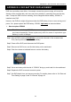
User manual Manual


APPENDIX 6 PIN CONFIGURATION
63
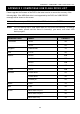
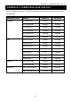
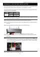
‧ For 4CH Model
* The D-Sub connector shown above is optional.
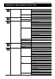
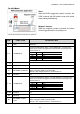
Siren:
When the DVR is triggered by alarm or motion,
the COM connects with NO and the siren with
strobe starts wailing and flashing.
Magnetic Contact:
When the magnetic contact is opened, the alarm
will be triggered and the recording is on.
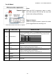
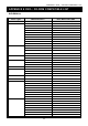
PIN FUNCTION DESCRIPTION
1~4
ALARM INPUT
Connect ALARM INPUT (PIN1 – 4) and GND (PIN5) connector with wires.
Once an alarm is triggered, the DVR will start recording and the buzzer
will be on.
PIN Alarm Corresponding video channel
PIN 1 1 CH1
PIN 2 2 CH2
PIN 3 3 CH3
PIN 4 4 CH4
*
5
GND GROUND
6
EXTERNAL ALARM
COM
Under the normal operation, COM disconnects with NO. But when any
alarm is triggered, COM connects with NO.
Attention: The voltage restriction is under DC24V 1A.
7
EXTERNAL ALARM
NO
Under the normal operation, COM disconnects with NO. But when any
alarm is triggered, COM connects with NO.
Attention: The voltage restriction is under DC24V 1A.
8
RS485-A
9
RS485-B
10~11
GND
GROUND