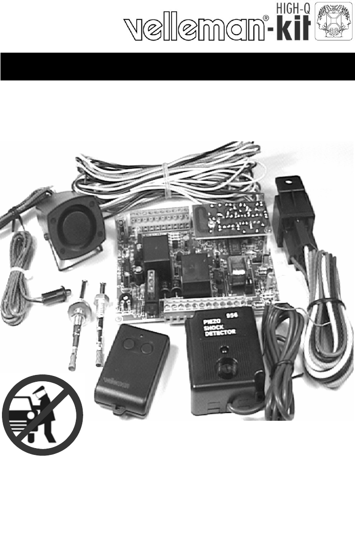
Remote controlled car alarm Total solder points: 88 + 68 + 367 Difficulty level: beginner 1 2 3 4 5 ⌧ advanced K3511 ILLUSTRATED ASSEMBLY MANUAL H3511IP-2
Features & specifications Features : Microprocessor technology. Multi-functional remote control operation. Audio and visual on/off indicators. Multifunction dashboard mounted LED. Automatic reset after alarm. Adjustable voltage drop (reaction to interior lighting). Voltage drop detection active immediately, or after 5 minutes. Direct alarm trigger input (direct alarm after triggering). Warning alarm trigger input (2 triggers within 15 seconds = alarm).
Assembly hints 1. Assembly (Skipping this can lead to troubles ! ) Ok, so we have your attention. These hints will help you to make this project successful. Read them carefully. 1.1 Make sure you have the right tools: • A good quality soldering iron (25-40W) with a small tip. • Wipe it often on a wet sponge or cloth, to keep it clean; then apply solder to the tip, to give it a wet look. This is called ‘thinning’ and will protect the tip, and enables you to make good connections.
Assembly hints 1.3 Soldering Hints : 1- Mount the component against the PCB surface and carefully solder the leads 2- Make sure the solder joints are cone-shaped and shiny 3- Trim excess leads as close as possible to the solder joint REMOVE THEM FROM THE TAPE ONE AT A TIME ! AXIAL COMPONENTS ARE TAPED IN THE CORRECT MOUNTING SEQUENCE ! Velleman hereby certifies that the device K3511 meets the essential requirements and all other relevant stipulations of directive 1999/5/ EG and 1995/5/EC.
Construction IMPORTANT The car alarm consist of three PCB’s, 1 for the remote control transmitter, 1 for the receiver and 1 for the main PCB. The receiver PCB is fitted to the main PCB. Tip: The pictures on the packaging can be used as a guideline. However, due to possible changes it is not 100% reliable. (A) Construction of the P6706 remote control transmitter Before mounting the components to the PCB it must first be checked that the PCB fits in the housing. Be careful of the small notch next to LD1.
Construction 7. Capacitive trimmer 12. LED (Check the polarity) CV : 1,5 - 5pF CV... 8. IC socket (Watch the position of the notch) + - IC1 : 18p 1 IC... 13. IC (Watch the position of the notch !) 9. Capacitors C1 : 2pF (2,2) C2 : 2pF (2,2) C3 : 330pF (331) C... IC1 : UM3758 - 120A 14. Sticker 10. Transistor Affix the supplied sticker to the housing. T1 : BF199 Velleman 433,92 MHz 7mm SRFCE 11.
Construction 15. Create your code The code can be set for a transmitter/receiver combination. There is a row of 9 coding islands for setting the code. The closest is near the IC legs. The code can be set by connecting one or more of these coding islands to a neighbouring island or a neighbouring + island using a jumper, or by not connecting them at all (leaving open).
Construction (B) Construction of the remote control receiver P3511R 1. Zener diode (Check the polarity) 4. IC socket. Watch the position of the notch. ZD... ZD1 : 4V3 ZD2 : 5V1 ZD3 : 5V1 IC1 : 8p IC... 2. Resistors (check the color code) 5. Capacitors C1 : 2pF (2,2) C2 : 2pF (2,2) C3 : 22pF C4 : 82pF C5 : 330pF (331) C6 : 330pF (331) C7 : 1µF (105 - 1µ) R...
Construction 8. Capacitive trimmer Solder side CV... Fig.8 CV1 : 5pF 9. LED (Check the polarity) 8mm SOLDER SIDE LD1 : 3mm RED 10.
Construction (C) Construction of the main PCB 3511 1. Jumperwire J 2. Diodes (Check the polarity) D... CATHODE D1 D2 D3 D4 D5 D6 D7 D8 D9 D10 D11 D12 : 1N4148 : 1N4148 : 1N4148 : 1N4148 : 1N4148 : 1N4148 : 1N4000 … 1N4007 : 1N4000 … 1N4007 : 1N4000 … 1N4007 : 1N4000 … 1N4007 : 1N4000 … 1N4007 : 1N4000 … 1N4007 3. Zener diode. Check the polarity! ZD1 : 2V4 ZD2 : 5V1 ZD3 : 18V ZD4 : 18V ZD5 : 18V ZD... CATHODE 4. Resistors (check the color code) R...
Construction 5. Axial coil C9 : 100nF C10 : 100nF L2 L... 10. Transistors L1 : 100µH (1 - 0 - 1 - A) 6. IC sockets (Watch the position of the notch) IC1 : 8p IC2 : 18p IC3 : 18p 1 IC... 7. Potentiometer RV1 RV1 : 4K7 / 5K (µ1 - 104) (µ1 - 104) T1 T2 T3 T4 T5 T6 T7 T8 T9 T10 T11 T12 T13 T14 : BC547 or eq. : BC547 or eq. : BC547 or eq. : BC547 or eq. : BC547 or eq. : BC547 or eq. : BC547 or eq. : BC547 or eq. : BC337 or eq. : BC337 or eq. : BC337 or eq. : BC337 or eq. : BC557 or eq.
Construction 13. Pin contacts 16. Voltage regulators VR1 : 7809 VR2 : 7805 cut 18mm JP1 : 3p JP2 : 3p JP3 : 3p JP4 : 3p 14. Electrolytic capacitors. Watch the polarity ! C11 : 1µF C12 : 1µF C13 : 1µF C14 : 1µF C15 : 1µF C17 : 1µF C18 : 1µF C19 : 22µF C20 : 220µ F C21 : 1000µF VR... 17. Fuse F1 : 15A Thin the PCB track with extra solder 18. Relays C... RY1 : FRA2C RY2 : FRA2C RY3 : V23033, FRA2C Thin the PCB track with extra solder 15. Diodes (Check the polarity) 19. IC’s.
Test & adjustment 20. Create your code See point 15 in transmitter construction “P6706”. (Pag. 7) 21. Final assembly Mount the receiver PCB “P3511R” on the main PCB “P3511” using the 20mm treaded rod. Check that the components of the main PCB and the receiver PCB do not touch each other. 22.
PCB 23. PCB P6706 24.
PCB 25.
BATTERY 12V - + NC A10 A9 A8 A7 A6 A5 A4 A3 A2 A1 IC1 18 SW2 A11 11 NC D1 D2 VSS TX OSC A12 12 14 17 13 16 RX MODE 15 UM3758-120A SW1 10 9 8 7 6 5 4 3 2 1 VDD R3 C3 R1 R2 C2 C1 R4 T1 CV L2 R5 ZD1 LD1 L1 Diagram 26.
R6 R5 C5 C3 C4 R7 T1 L2 R3 R1 L1 C1 CV1 R4 C6 R8 ZD1 C7 A1 R9 1 A1,A2 = IC1 3 2 R10 C2 4 8 7 LD1 A2 ZD2 6 5 R11 R13 R12 R2 ZD3 GND Rx OUT +9V Diagram 27.
Diagram 28.
VELLEMAN KIT NV Legen Heirweg 33 9890 Gavere Belgium Europe Info ?: http://www.velleman.