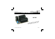
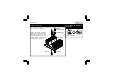
Total solder points: 57 Difficulty level: beginner 1 2 3 4 5 advanced 3 TO 30VDC / 3A POWER SUPPLY K7203 ased ur kits, b V.
Features This kit is meant as an auxiliary or as a permanent power supply for all common Velleman kits based on a stabilized DC voltage between 3 and 30V provided that the consumption does not exceed 3A. Of course this power supply unit can be used for other purposes, as long as the maximum specifications are taken into account. Technical data : Short circuit protected Overload protected Heatsink included Output voltage: adjustable 3 to 30V stabilized. Output current: max. 3A Output ripple voltage: 0.5mV.
Assembly hints 1. Assembly (Skipping this can lead to troubles ! ) Ok, so we have your attention. These hints will help you to make this project successful. Read them carefully. 1.1 Make sure you have the right tools: • A good quality soldering iron (25-40W) with a small tip. • Wipe it often on a wet sponge or cloth, to keep it clean; then apply solder to the tip, to give it a wet look. This is called ‘thinning’ and will protect the tip, and enables you to make good connections.
Assembly hints 1.3 Soldering Hints : 1- Mount the component against the PCB surface and carefully solder the leads 2- Make sure the solder joints are cone-shaped and shiny 3- Trim excess leads as close as possible to the solder joint AXIAL COMPONENTS ARE TAPED IN THE CORRECT MOUNTING SEQUENCE ! REMOVE THEM FROM THE TAPE ONE AT A TIME ! You will find the colour code for the resistances and the LEDs in the HALG (general manual) and on our website: http://www.velleman.be/common/service.
Construction 1. Resistors 3. Capacitors. 6. 5W resistor. R... R6 : 0.18E C... R1 : 8K2 (8 - 2 - 2 - B) R2 (Uout = output voltage) Uout 3...8V : 5K6 (5 - 6 - 2 - B) Uout 8...30V : 2K2 (2 - 2 - 2 - B) R3 : 680 (6 - 8 - 1 - B) R4 : 1K (1 - 0 - 2 - B) R5 : 82K (8 - 2 - 3 - B) 2. IC sockets, Watch the position of the notch ! C1 : 470pF (471) C2 : 100nF (104) C3 : 100nF (104) 2mm 7. Screw connectors 4. Resistor trimmer RV1 RV1 : 10K 5. Diodes.
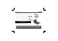
Construction 9. Power transistor 10. IC. Watch the position of the notch! M3 NUT LOCK WASHER T1 : MJ3001 or 2N6284G Apply some thermo-conducting pasta to the bottom side of the transistor and mount it on the PCB simultaneously with the cooling profile following the instructions in the figure 1.0. TRANSISTOR IC1 : UA723D HEATSINK PCB Fig 1.
Assembly into a housing 11. Assembly into a housing Depending on the transformer used, one may chose one of two housings with the following reference nr. for ordering: L750 or L760. If the circuit is to be integrated into another housing, it must be provided with ventilation holes (one may make these holes oneself), necessary for the release of the heat developed. If a metal housing is used, it must be earthed for security purposes. Make sure the cooling body does not touch the housing.
Connection 12. Connection Depending on the output voltage needed, one should chose the right transformer for connection to the circuit according to the table in the parts list. If one choses too high an input voltage, it may well be so that the power transistor is overheated. The secondary winding of the transformer is connected to the AC points. It may be that the transformer has two secondary windings which should be connected either in parallel or in series.
Connection L F TRANSFORMER MAINS AC N AC GND LOAD - Desired regulated output voltage 3...5V R2 5...8V 5K6 8...13V 2K2 13...15V 2K2 15...18V 2K2 +OUT K7203 + Desired transformer Desired fuse 230VAC Desired fuse 110VAC 309 160mA Slow 315mA Slow 12V / 50VA - 5012 250mA Slow 500mA Slow 15V / 50VA - 5015 250mA Slow 500mA Slow 18V / 80VA - 8018 400mA Slow 800mA Slow 22V / 80VA - 80220 400mA Slow 800mA Slow ordercode only @230VAC 5K6 9V / 30VA - 18...
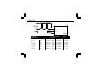
PCB 13. PCB layout.
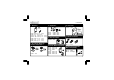
Diagram 14. Diagram AC 6A6 D1 6A6 D3 INPUT D2 6A6 C5 C2 6A6 10000u 100n D4 V+ 12 AC NC NC NC NC 1 8 9 14 VC R5 82K 11 OUT 10 CL 2 REF RV1 10K NON INV 680 D5 R6 0.
VELLEMAN Components NV Legen Heirweg 33 9890 Gavere Belgium Europe www.velleman.be www.velleman-kit.com Modifications and typographical errors reserved © Velleman Components nv. H7203IP - 2010 - ED1 (Rev.