Total solder points: 274 Difficulty level: beginner 1 2 3 4 5 advanced PIC® programmer and experiment board K8048 ® Microchip gramming ro p r fo le ollers.
This device complies with Part 15 of the FCC Rules provided the enclosed instructions are followed to the letter. Use of the device is subject to the following conditions: (1) this device must not cause harmful interference and (2) the operation of this device should not be influenced by unwanted interference. More information about FCC can be look at http://www.fcc.
Features & Specifications Features: Suitable for programming Microchip® FLASH PIC(tm) microcontrollers Supports 4 different 300 mil.
Assembly hints 1. Assembly (Skipping this can lead to troubles ! ) Ok, so we have your attention. These hints will help you to make this project successful. Read them carefully. 1.1 Make sure you have the right tools: • A good quality soldering iron (25-40W) with a small tip. • Wipe it often on a wet sponge or cloth, to keep it clean; then apply solder to the tip, to give it a wet look. This is called ‘thinning’ and will protect the tip, and enables you to make good connections.
Assembly hints 1.
Construction 1. Diodes. Watch the polarity! D1 D2 D3 D4 D5 D6 D7 : : : : : : : 1N4007 1N4148 1N4148 1N4148 1N4148 1N4148 1N4148 R... CATHODE 2. Zenerdiodes. Watch the polarity! CATHODE ZD1 : 8V2 6 3. Resistors ZD... D...
Construction 5. Push buttons SW1 SW2 SW3 SW4 SW6 KRS0611 6. IC sockets, Watch the position of the notch! 7. LEDs. Watch the polarity ! LD1 : 3mm LD2 : 3mm LD3 : 3mm LD4 : 3mm LD5: 3mm LD6 : 3mm LD8 : 3mm LD7 : 3mm COLOR= 2...5 9. Voltage regulator VR1 : UA78L12 VR2 : UA78L05 VR... LD... RED CATHODE 10. Header GREEN 8. Transistors.
Construction SK3 : 5P 12. DC - Jack 15. Electrolytic Capacitor. Watch the polarity ! SK1 : 15VDC (Power) C... 13. Sub D - connector C1 : 220µF 11. Blinking LED. Watch the polarity! 16. Switch SK2 : RS232 (9p female) LD1 14. Quartz crystal CATHODE X1 : 4MHz LD9 : Blinking red (5mm) X... SW5 : 3 pos.
Construction 17. Rubber feet Mount the rubber feet on the solder side of the PCB, see fig 1.0. FIG 1.0 18. Software installation • Place the Velleman® software CD in your CD-ROM player. • Select ‘Browse through this CD for other Velleman software’ (this message will not be displayed on your screen • • • • if ‘AUTORUN’ is not activated. Select the right folder on the CD with Windows Explorer). Select the ‘Velleman Kits’ folder. Select the ‘K8048’ folder. Run the ‘INSTALL_K8048.
Schematic diagram 19. Schematic diagram.
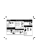
PCB 20.
VELLEMAN Components NV Legen Heirweg 33 9890 Gavere Belgium Europe www.velleman.be www.velleman-kit.com Modifications and typographical errors reserved © Velleman Components nv.