
User manual
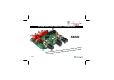

5
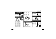
R1 : 1K (1 - 0 - 2 - B)
R2 : 100K (1 - 0 - 4 - B)
R16 : 10K (1 - 0 - 3 - B)
R17 : 10K (1 - 0 - 3 - B)
R18 : 10K (1 - 0 - 3 - B)
R19 : 10K (1 - 0 - 3 - B)
R20 : 10K (1 - 0 - 3 - B)
Hint for R21 to R24
Modify the resistances marked RF
and RA to increase the input sen-
sitivity (more amplification).
The formula is:
amplification = (RF/RA) + 1
E.g. to double the amplification because
the input of the connecting device is too
weak, mount 100K for RF (R22 and
R23).
R21 : 100K (1 - 0 - 4 - B)
R22 : 1K (1 - 0 - 2 - B)
R23 : 1K (1 - 0 - 2 - B)
R24 : 100K (1 - 0 - 4 - B)
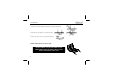
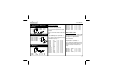
3. Resistors
R...
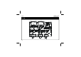
Construction
D1 : 1N4007
D2 : 1N4007
D3 : 1N4007
D4 : 1N4007
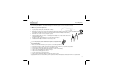
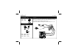
2. Diodes. Watch the polarity !
D...
CATHODE
ZD1 : 9V1
ZD2 : 9V1
1. Zenerdiodes. Watch the
polarity !
CATHODE
ZD...
Hint for R2 and R4:
To weaken the input (divide)
E.g. to connect the input with an amplifi-
er output.
Choose an inferior value for R2 and
R4.
The dividing factor = (R1/R2) + 1
E.g. a value of 100Ω for RD (R2 and R4)
will divide the input by 11.
R3 : 1K (1 - 0 - 2 - B)
R4 : 100K (1 - 0 - 4 - B)
R5 : 10 (1 - 0 - 0 - B)
R6 : 10 (1 - 0 - 0 - B)
R7 : 1K (1 - 0 - 2 - B)
R8 : 1K (1 - 0 - 2 - B)
R9 : 3K3 (3 - 3 - 2 - B)
R10 : 1K (1 - 0 - 2 - B)
R11 : 1K (1 - 0 - 2 - B)
R12 : 10 (1 - 0 - 0 - B)
R13 : 3K3 (3 - 3 - 2 - B)
R14 : 3K3 (3 - 3 - 2 - B)
R15 : 10K (1 - 0 - 3 - B)