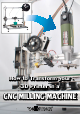
How to Transform your 3D Printer in a CNC MILLING MACHINE
How to Transform your 3D Printer in a CNC milling machine W e can finally presents you a tutorial on how to modify our 3D printer K8200 to transform it in a perfect CNC milling machine, to be used for the production of PCBs, by incision. In addition, we also show you the procedures to obtain the G-Code file required for the machine to perform the contouring of the slopes and the drilling of the base: this starting from any Gerber file or from a project made with EAGLE software.
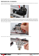
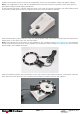
MECHANICAL MODIFICATION TO BE MADE TO K8200 TO ALLOW MOUNTING A ROTARY TOOLS T he first step is to use the K8200 to print the bracket for the mandrel whose file can be freely downloaded from the following link (http://www.thingiverse.com/thing:225465). The bracket, fitted out with a collar with a 20 mm hole, allows you to attach to the structure any electric-mandrel with cylindrical collar having the same diameter.
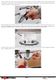
MECHANICAL CHANGES Insert an M5 galvanized nut in the upper arm hollow taking advantage of the opening between the aluminum profile and the front plastic frame. The next operation concerns the displacement of the extruder from the original position. The extruder is fixed to a bracket which, in turn, is attached to the horizontal printer arm using 2 M5 screws.
Also loosen the two fan screws indicated by the red arrows. Move the extruder over the arm completely to the left (as shown in photo). Move to the same side also the fan. In this way the nozzle of the extruder will be sufficiently separated from the work surface remaining locked to the structure. Place, in a hole of the bracket, an M5 screw (indicated by the red arrow) which will be screwed into the M5 nut previously inserted in the arm.
Tighten the involved screws to secure the components to the arm and reattach cables with plastic clamps. Note: it is suggested to cover with a transparent film the entire extruder to protect it from dust which is generated during the PCB milling operations. In the bracket front part a cylinder head screw M6 x 35 must be inserted (complete with 2 flat washers and self-locking nut M6) that will serve to tighten the collar to lock the electric mandrel.
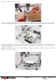
Install, under the printer arm, the bracket that will support the electric mandrel with the two cylinder head screws M5 x 40 previously inserted and bolted to the two square nuts already in the arm provided for fixing the extruder as shown in the photo below.
Tighten the bracket screws just enough. Apply on the printing plate, with a little bit of double-sided adhesive, a square glass plate of +/- 200 mm side and about 3 mm thick. Alternatively, you can also use a standard square-shaped mirror that can be purchased. Attach to the glass / mirror a “sacrificial” plan of suitable thickness (about 1 cm) in order to drill the holes of the PCB without damaging or breaking the tool. That plan could be MDF, forex, plywood, etc. … no humps, bumps or other deformations.
Tip: use a Set square or a caliper body to verify the plan regularity. T he mechanical changes to K8200 end here. In order to use the K8200 as CNC milling machine you must also update the firmware of the PCB printed circuit board, so that the Z axis could assume negative values respect to the position zero. To do this, download this firmware (http://3dprint.elettronicain.it/wpcontent/uploads/2013/12/Marlin_Futura_A10_Piatto_ON_LCD_ON_MILL_ON.zip).
Creating G-Code via EAGLE software To create a PCB with 3D printer, by milling, it is necessary to have the G-Code files for the tracks patterning and for the holes relating to the printed circuit board itself. In this section we describe how to obtain these G-Code files using a specific plugin for the popular PCB design software “EAGLE”. Note: This operation can be done only if the PCB you want was created with EAGLE .
PCB- gcode parameters configuration - Start PCB- gcode typing this command in the command line: run pcb-gcode-setup After sending it you will see the following window in which you have several configuration folders (Generation Options, Machine, GCode Style, GCode options…): In the “Generation Options” folder check the two entries under “Top Side” and the entry Single pass of “Isolation”. This allows to make tracks patterning with a single pass of the tool.
In the folder “GCode Style” you can set the generated G -code style more suited to your machine (we chose C:/Program Files (x86)/EAGLE-6.5.0/ulp/profiles/generic.pp). The folder ”GCode Options” allows to choose whether to insert comments in the generated G -code (in our case do not check any item), if use a custom G -code and more.
Repetier-Host settings and G-Code import/modifications Open Repetier Host, select “CNC Router” (from “Printer Settings” in the upper right, indicated by the red arrow). Set the parameters as follows: Load in Repetier -host the Gcode xxx.top.etch.nc or the file for the tool route of the PCB you want to realize (xxx is the name assigned to the PCB, in this case “alim”).
In the 3D window will appear the outlines of the PCB tracks that will be made by milling (Show Filament and Show route must be operative). From G -Code Editor delete the initial lines in which there are round brackets (in this case only the second command line). Click on the dropdown menu of G -Code Editor and select “initial code” .
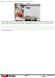
Preparation of CNC machine Insert and lock in the electric mandrel pliers the milling burin, whose bit size must be the same of that defined in the settings of PCB- gcode (hard metal burin is recommended as the fiberglass is highly abrasive!), and let it stick out as less as possible, in order to avoid vibrations and an excessive run out. Pull the tool as close as possible to the sacrificial plane so as to touch it. Move the plane in all directions to make sure that the distance from the tool is constant.
Start milling tracks pattern Lower the Z-axis (using the Repetier-Host manual control) just enough to pull the chisel close to the base (about 2-3 mm) and then adjust the X and Y axes to position the tool at the origin of the PCB that you want to mill. Now, turn on the electric mandrel, set the maximum speed then manually rotate (very slowly) the Z motor shaft to lower the machine arm until it touches the PCB with the burin bit.
Creating G-Code from gerber files How to create the G-code files from any gerber file (using PCBMill software) necessary to create a PCB with 3D printer, by milling. To create a PCB with 3D printer, by milling, you need the G-Code files for the tracks patterning and for the holes pertaining to the printed circuit board itself.
Creating the G-Code files Before using PCBMill, it is necessary to have available the gerber file related to the PCB that you want realize by milling. Note: The Gerber file must be related to the “mirrored” printed circuit board in the same way that the “copper side” (usually defined as Bottom Copper) remains face-up, necessary condition for a correct milling. From the File menu, select Open gerber and open the files relating to the tracks (e.g. Bottom Copper.gbr).
Settings Repetier-Host and import/ G-Code modifications Open Repetier-Host, select “CNC Router” (from “Printer Settings” in the upper right, indicated by the red arrow): Set the parameters as follows: To correctly display both the incision and the tool track select “Show Filament” and “Travel Show”.
Import in the G -Code Editor of Repetier-Host (with a simple copy and paste) the G-Code on the milling of the tracks, previously generated with PCBMill, seen in the following image: The only thing to take care of is to remove the first 5 lines of G-Code, those that begin with % %~~~~~~~~~~~~~~~~~~~~~~~~~~~~~~~~~~~~~~~~~~~~~~ ~~~~~~ % File was created with V1.
On the right, select the tab G-Code Editor, open the drop- down menu and select Start Code: Enter the following control lines: G92 X0 Y0 Z0; offset of the coordinate system (set the starting point as home) G01 F500; linear movement (sets a movement speed of 500 mm/min) The same thing must be done for the End Code by entering the control: G01 X0 Y0 F1200; linear motion (back to the point X0 Y0 with a speed of 1200 mm/min).
Attach the copper strip to work on the sacrificial level, with the double-sided tape. After attaching the base with double-sided adhesive is necessary to make a fine adjustment by acting on the knobs, so that the base is coplanar with the tool.
Creating G-Code file relating to the holes From the PCBMill File menu, select Open drill: This will open a menu in which you will have to select “Read drill file”: Load the file relating to holes of the PCB whose tracks patterning has been carried out by milling (e.g. Drill Data.drl). The software will automatically create the corresponding G-Code showing the holes that will be made with red dots.
Export the file by selecting Export -> Drill G-Code. The file generated by PCBMill visible in the image below must be imported into G-Code Editor of Repetier – Host (with a simple copy and paste). In this case, the imported file should not be modified. In the 3D view window you will see the paths of the drilling tool (Show Filament and Show Route must be operative).
After tightening the mandrel, pull down again the Z-axis to position the bit at about 1-2 mm from the copper plate. Now, turn on the electric mandrel and rotate manually (very slowly) the Z motor shaft lowering the machine arm until it touches the PCB with the drill bit. The contact point should coincide with the contact point previously defined with the milling tool.