
Data Sheet

Sensors
16 Freescale Semiconductor
MMA8452Q
5.10.1 I
2
C Operation
The transaction on the bus is started through a start condition (START) signal. START condition is defined as a HIGH to LOW
transition on the data line while the SCL line is held HIGH. After START has been transmitted by the Master, the bus is considered
busy. The next byte of data transmitted after START contains the slave address in the first 7 bits, and the eighth bit tells whether
the Master is receiving data from the slave or transmitting data to the slave. When an address is sent, each device in the system
compares the first seven bits after a start condition with its address. If they match, the device considers itself addressed by the
Master. The 9th clock pulse, following the slave address byte (and each subsequent byte) is the acknowledge (ACK). The
transmitter must release the SDA line during the ACK period. The receiver must then pull the data line low so that it remains
stable low during the high period of the acknowledge clock period.
A LOW to HIGH transition on the SDA line while the SCL line is high is defined as a stop condition (STOP). A data transfer is
always terminated by a STOP. A Master may also issue a repeated START during a data transfer. The MMA8452Q expects
repeated STARTs to be used to randomly read from specific registers.
The MMA8452Q's standard slave address is a choice between the two sequential addresses 0011100 and 0011101. The
selection is made by the high and low logic level of the SA0 (pin 7) input respectively. The slave addresses are factory
programmed and alternate addresses are available at customer request. The format is shown in Table 9.
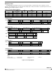
Single Byte Read
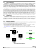
The MMA8452Q has an internal ADC that can sample, convert and return sensor data on request. The transmission of an
8-bit command begins on the falling edge of SCL. After the eight clock cycles are used to send the command, note that the data
returned is sent with the MSB first once the data is received. Figure 12 shows the timing diagram for the accelerometer 8-bit I
2
C
read operation. The Master (or MCU) transmits a start condition (ST) to the MMA8452Q, slave address ($1D), with the R/W bit
set to “0” for a write, and the MMA8452Q sends an acknowledgement. Then the Master (or MCU) transmits the address of the
register to read and the MMA8452Q sends an acknowledgement. The Master (or MCU) transmits a repeated start condition (SR)
and then addresses the MMA8452Q ($1D) with the R/W bit set to “1” for a read from the previously selected register. The Slave
then acknowledges and transmits the data from the requested register. The Master does not acknowledge (NAK) the transmitted
data, but transmits a stop condition to end the data transfer.
Multiple Byte Read
When performing a multi-byte read or “burst read”, the MMA8452Q automatically increments the received register address
commands after a read command is received. Therefore, after following the steps of a single byte read, multiple bytes of data
can be read from sequential registers after each MMA8452Q acknowledgment (AK) is received until a no acknowledge (NAK)
occurs from the Master followed by a stop condition (SP) signaling an end of transmission.
Single Byte Write
To start a write command, the Master transmits a start condition (ST) to the MMA8452Q, slave address ($1D) with the R/W bit
set to “0” for a write, the MMA8452Q sends an acknowledgement. Then the Master (MCU) transmits the address of the register
to write to, and the MMA8452Q sends an acknowledgement. Then the Master (or MCU) transmits the 8-bit data to write to the
designated register and the MMA8452Q sends an acknowledgement that it has received the data. Since this transmission is
complete, the Master transmits a stop condition (SP) to the data transfer. The data sent to the MMA8452Q is now stored in the
appropriate register.
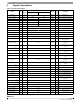
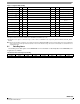
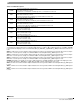
Table 9. I
2
C Address Selection Table
Slave Address (SA0 = 0) Slave Address (SA0 = 1) Comment
0011100 (0x1C) 0011101 (0x1D) Factory Default