
Data Sheet

Sensors
26 Freescale Semiconductor
MMA8452Q
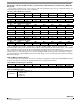
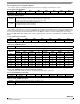
0x14: P_L_THS_REG Portrait/Landscape Threshold and Hysteresis Register
This register represents the Portrait to Landscape trip threshold.
:
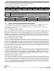
6.3 Motion and Freefall Embedded Function Registers
The freefall/motion function can be configured in either freefall or motion detection mode via the OAE configuration bit (0x15
bit 6). The freefall/motion detection block can be disabled by setting all three bits ZEFE, YEFE, and XEFE to zero.
Depending on the register bits ELE (0x15 bit 7) and OAE (0x15 bit 6), each of the freefall and motion detection block can
operate in four different modes:
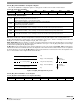
Mode 1: Freefall Detection with ELE = 0, OAE = 0
In this mode, the EA bit (0x16 bit 7) indicates a freefall event after the debounce counter is complete. The ZEFE, YEFE, and
XEFE control bits determine which axes are considered for the freefall detection. Once the EA bit is set, and DBCNTM = 0, the
EA bit can get cleared only after the delay specified by FF_MT_COUNT. This is because the counter is in decrement mode. If
DBCNTM = 1, the EA bit is cleared as soon as the freefall condition disappears, and will not be set again before the delay
specified by FF_MT_COUNT has passed. Reading the FF_MT_SRC register does not clear the EA bit. The event flags (0x16)
ZHE, ZHP, YHE, YHP, XHE, and XHP reflect the motion detection status (i.e. high g event) without any debouncing, provided that
the corresponding bits ZEFE, YEFE, and/or XEFE are set.
Mode 2: Freefall Detection with ELE = 1, OAE = 0
In this mode, the EA event bit indicates a freefall event after the debounce counter. Once the debounce counter reaches the
time value for the set threshold, the EA bit is set, and remains set until the FF_MT_SRC register is read. When the FF_MT_SRC
register is read, the EA bit and the debounce counter are cleared and a new event can only be generated after the delay specified
by FF_MT_CNT. The ZEFE, YEFE, and XEFE control bits determine which axes are considered for the freefall detection. While
EA = 0, the event flags ZHE, ZHP, YHE, YHP, XHE, and XHP reflect the motion detection status (i.e., high g event) without any
debouncing, provided that the corresponding bits ZEFE, YEFE, and/or XEFE are set. The event flags ZHE, ZHP, YHE, YHP, XHE,
and XHP are latched when the EA event bit is set. The event flags ZHE, ZHP, YHE, YHP, XHE, and XHP will start changing only
after the FF_MT_SRC register has been read.
Mode 3: Motion Detection with ELE = 0, OAE = 1
In this mode, the EA bit indicates a motion event after the debounce counter time is reached. The ZEFE, YEFE, and XEFE
control bits determine which axes are taken into consideration for motion detection. Once the EA bit is set, and DBCNTM = 0,
the EA bit can get cleared only after the delay specified by FF_MT_COUNT. If DBCNTM = 1, the EA bit is cleared as soon as the
motion high g condition disappears. The event flags ZHE, ZHP, YHE, YHP, XHE, and XHP reflect the motion detection status
(i.e., high g event) without any debouncing, provided that the corresponding bits ZEFE, YEFE, and/or XEFE are set. Reading the
FF_MT_SRC does not clear any flags, nor is the debounce counter reset.
Mode 4: Motion Detection with ELE = 1, OAE = 1
In this mode, the EA bit indicates a motion event after debouncing. The ZEFE, YEFE, and XEFE control bits determine which
axes are taken into consideration for motion detection. Once the debounce counter reaches the threshold, the EA bit is set, and
remains set until the FF_MT_SRC register is read. When the FF_MT_SRC register is read, all register bits are cleared and the
debounce counter are cleared and a new event can only be generated after the delay specified by FF_MT_CNT. While the bit
EA is zero, the event flags ZHE, ZHP, YHE, YHP, XHE, and XHP reflect the motion detection status (i.e., high g event) without
any debouncing, provided that the corresponding bits ZEFE, YEFE, and/or XEFE are set. When the EA bit is set, these bits keep
their current value until the FF_MT_SRC register is read.
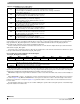
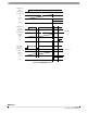
0x14: P_L_THS_REG Register (
Read Only
)
Bit
7
Bit
6
Bit
5
Bit
4
Bit
3
Bit
2
Bit
1
Bit
0
P_L_THS[4] P_L_THS[3] P_L_THS[2] P_L_THS[1] P_L_THS[0] HYS[2] HYS[1] HYS[0]
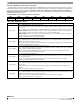
Table 24. P_L_THS_REG Description
P_L_THS[7:3] Portrait/Landscape Fixed Threshold angle = 1_0000 (45°).
HYS[2:0]
This is a fixed angle added to the threshold angle for a smoother transition from Portrait to Landscape and Landscape to
Portrait. This angle is fixed at ±14°, which is 100.
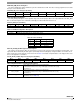
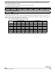
Table 25. Trip Angles with Hysteresis for 45° Angle
Hysteresis
Register Value
Hysteresis
± Angle Range
Landscape to Portrait
Trip Angle
Portrait to Landscape
Trip Angle
4 ±14 59° 31°