
Data Sheet
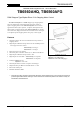
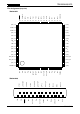

TB6560AHQ/AFG
2014-10-01
8
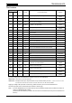
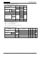
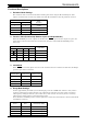
Electrical Characteristics
(T
a
=
25°C, V
DD
=
5 V, VM
=
24 V)
Characteristics Symbol Test Condition Min Typ. Max Unit
Output ON-resistance
TB6560AHQ
Ron
U1H
I
OUT
= 1.5 A
0.3 0.4
Ω
Ron
L1H
0.3 0.4
TB6560AFG
Ron
U1F
I
OUT
= 1.5 A
0.35 0.5
Ron
L1F
0.35 0.5
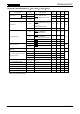
A-/B-phase chopping current (Note 1)
4W1-2-
phase
excitation
2W1-2-
phase
excitation
1-2-
phase excitation
Vector
θ = 0
TQ1 = L, TQ2 = L
100
%
θ = 1/16 100
2W1-2-
phase
excitation
θ = 2/16 93 98 100
θ = 3/16 91 96 100
2W1-2-
phase
excitation
θ = 4/16 87 92 97
θ = 5/16 83 88 93
2W1-2-
phase
excitation
θ = 6/16 78 83 88
θ = 7/16 72 77 82
2W1-2-
phase
excitation
1-2-
phase excitation
θ = 8/16 66 71 76
θ = 9/16 58 63 68
2W1-2-
phase
excitation
θ = 10/16 51 56 61
θ = 11/16 42 47 52
2W1-2-
phase
excitation
θ = 12/16 33 38 43
θ = 13/16 24 29 34
2W1-2-
phase
excitation
θ = 14/16 15 20 25
θ = 15/16 5 10 15
2-phase excitation 100
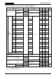
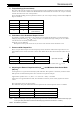
Reference voltage V
NF
TQ1, TQ2 = L (100 %)
OSC = 100 kHz
450 500 550 mV
Output transistor switching characteristics
(Note 2)
t
r
R
L
= 10 Ω, V
NF
= 0.5 V
1
µs
t
f
1
Delay time (Note 2)
t
pLH
RESET
to output 1
t
pLH
ENABLE to output
3
t
pHL
2
Output leakage current
Upper side I
LH
VM = 40 V
1
µA
Lower side I
LL
1
Note 1: Relative to the peak current at θ = 0.
Note 2: Not tested in production.