
Data Sheet
Warning:
1、 ! 6560
.
2、
、
Check the connection twice The Tb
chipset can be damaged if the motor or the
power supply are not connected properly
Dont apply a motor that its rated current
is more than 3A to this driver.
3 Do not set the current more than the motor
rated current!
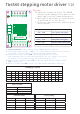
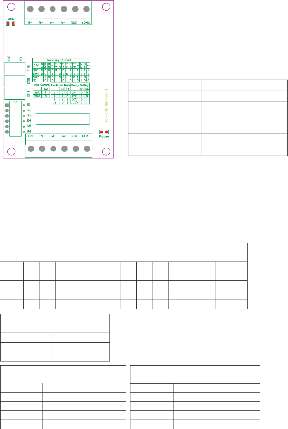
Tb6560 stepping motor driver V20
Photocouplers
Running Current
()A
0.3 0.5 0.8 1 1.1 1.2 1.4 1.5 1.6 1.9 2 2.2 2.6 3
SW1
OFF OFF OFF OFF OFF ON OFF ON ON ON ON ON ON ON
SW2
OFF OFF ON ON ON OFF ON OFF OFF ON OFF ON ON ON
SW3
ON ON OFF OFF ON OFF ON ON OFF OFF ON ON OFF ON
S1
ON OFF ON OFF ON ON OFF ON OFF ON OFF ON OFF OFF
Stop Current
S2
20% ON
50% OFF
Excitation Mode
S3 S4
whole
OFF OFF
half
ON OFF
1/8
ON ON
1/16
OFF ON
Decay Setting
S5 S6
0% OFF OFF
25% ON OFF
50% OFF ON
100% ON ON
、,
、,
、
、
25V
3CLK
4
CW
5EN
The normal input voltage is if it is more than 5V,than a series resistor
is needed. this resistance is 1K case 12V and 2.4K case 24V.
when pulse is applied to the stepping motor will rotate,
and stop when there is none,and the motor driver will change its current
to the half mode as setting to hold the motor still.
Motor rotate clockwise when is low level and counterclockwise when
is high level.
Motor is enable when is low level and disable when EN is high leve.
CW
1、, 。6 input terminals can be connected as common anode or cathode
current
Note:
Step
Wiring Terminal symbol Description
+24V,GND Power positive and negative
A+,A- Motor phase A
B+,B- Motor phase B
CLK+,CLK- Pulse positive and negative
CW+,CW- Direction positive and negative
EN+,EN- Enable positive and negative