
User manual


11
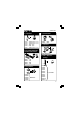
Connections / settings
5 digital inputs (e.g. push button, switch, relay contact, ...).
Input is generally "high" (1), connection to GND makes the
input "low" (0)
Analogue inputs (e.g. temperature sensor, potentiometer, ...)
If the jumper is mounted, then you can use the internal
voltage and adjust it using RV2/RV1. If the jumper is not
mounted you must use the external voltage A2/A1.
Setting of the internal voltage for input A1.
Setting of the internal voltage for input A2.
Address selection, open = 1, closed = 0
Analogue outputs.
Digital outputs
USB connection to computer
Select the correct address in the test program
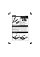
DIGITAL OUTPUTS
8 open collector contacts, to be connected with suitable inputs.
ANALOGUE OUTPUTS
2 analogue outputs with an output voltage between 0 and +5V
(impedance 1K5).
2 PWM outputs with a pulse width modulation between 0 and
100%.
REMARK: the analogue outputs and PWM outputs are al-
ways activated /deactivated together.
1
2
3
4
5
6
7
8
9
10