
User manual


14
Test procedure
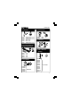
You can now simulate the inputs via push buttons Inp1 through
Inp5. The matching check box remains ticked off as long as you
keep one of the push buttons pressed down.
Always tick off the check box for the matching output if you wish
to test a digital output.
You can also conduct this procedure automatically : press the
'output test' button or activate all outputs with the 'Set all digital'
button. Press the 'output test' button to test all digital outputs
automatically.
Test the analogue outputs with the 'set all analog' button and
modify the output voltage with DA1 & DA2
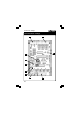
Counter 1 & 2 are hardware integrated 16-bit converters, they
are triggered by INP1 & INP2.
You can test the counter with push buttons Inp1 and Inp2 : the
counter adds 1every time one of these two buttons is pressed.
The debouncing control allows you to determine the reaction
time of the counter (0ms - 2ms - 10ms - 1000ms).
You can use the internal analogue voltage to simulate the ana-
logue input via potentiometers ATT1 (RV1) & ATT2 (RV2).
The scroll bars AD1 & AD2 change on the screen whenever you
adjust the position of the potentiometers. The "digital" value (0 to
255) of this internal analogue voltage can be read directly under
the scroll bars
.