
Manual


5
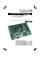
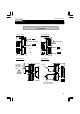
1 USB-connector
Connection of the VM140 with the USB port of your PC
2 12VDC
Power supply connection. Connect a 12V non-regulated adapter supplying
min. 300mA
3
Digital inputs
1, 2, 3, 4
4
Digital inputs
5, 6, 7, 8
5
Digital outputs
1, 2, 3, 4
These outputs are open collector outputs. When active, the transistors in IC4
will conduct and a “connection” will be established between GND and the
output in question. The charge you wish to feed, like a LED, relay …, must
receive an external tension. Connect the “CLAMP” connection with the + of
this external power supply so as to protect the transistor array.
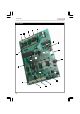
6
Digital outputs
5,6,7,8
7
Analogue inputs
1,2,3,4
These are measuring points with which you can digitalize and read out an
analogue voltage through the PC. The analogue inputs expect a DC voltage
between 0 and 5V or between 0 and 10V. Select with the jumpers AD1 to AD8
(see n° 13). Attention: Supplying a voltage to the A/D inputs higher than 5 or
10V can cause irrevocable damage to the VM140 (IC10/11)!
8
Analogue inputs
5,6,7,8
9
Analogue outputs
1,2,3,4
Determination with software of the DC voltage on these outputs. Depending
on the jumpers DA1 to DA8 you can establish this voltage between 0 and 5V
or between 0 and 10V. On pin 2 of this connector (SK9) you can also find the
PWM output. The PWM output is an open collector output whose pulse width
is adjustable.
10
Analogue outputs
5,6,7,8
11
Addressing of the
selection jumpers
With the jumpers A1, A2 and A3 you can attribute a unique address to each
connected VM140. Up to 8 boards can be connected. If you have only 1
VM140, establish its address as “0”.
12
Max. A/D voltage
With the jumpers AD1-AD8 you can select the voltage range for the corre-
sponding A/D inputs between 0 to 5V (closed) or 0 to 10V (open).
13
Max. D/A output
voltage
With the jumpers DA1-DA8 you can select the max. voltage range for the
corresponding D/A outputs between 0 to 5V (open) or 0 tot 10V (closed)
14
PWM control LED
This LED will light if the PWM output is active. The brightness of the LED is
analogous to the pulse/pause relation.
15
CPU “run mode”
LED
Lights when the CPU of the VM140 (IC6) is functioning correctly.
16 CPU RC/TX LED
This LED lights in case of data exchange between the CPU and the USB
interface controller (IC3). If the LED does not light when the board is
powered, check the USB controller (IC3) or the optical separation (IC1 & 2)
for faults.
17 “POWER ON” LED
Lights in case of the presence of the 5V power supply for the USB controller.
Attention: The VM140 is powered through the USB port of your PC and does
not guarantee operation of the power supply section of the VM140’s CPU and
I/O section.
18
“USB” LED
Blinks during USB connection and lights at every successful connection be-
tween the USB chip in your PC and the VM140.
19
Digital input indica-
tion
These LEDs turn out when a corresponding input goes “LOW” (connection of
the input with GND) through an external contact or an external open collector
input.
20
Digital output indi-
cation
These LEDs light if a corresponding output is active, i.e. when a connection is
established between an output pin and GND (open collector output).
Inputs need to go “LOW” externally to activate (connect with the GND).
Connections