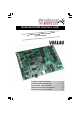
Extended USB interface card l USB I/O universa 33 l fu se u ly A practical ard.
Velleman Components N.V. Legen Heirweg 33 9890 Gavere, Belgium http://www.velleman http://www.velleman--kit.com Kits & Instruments Service Forum : http://forum.velleman.
Features & specifications This computer interface board has a total of 33 inputs / outputs, including analogue / digital and a PWM output. The connection to the computer via the USB port is galvanically-optically isolated, so that damage to the computer is impossible thus providing a high level of secure implementation. All communication routines are contained in a Dynamic Link Library (DLL).
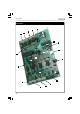
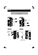
7 10 9 8 14 13 12 15 2 16 19 17 1 18 11 3 4 5 4 20 6 Connections Connections
Connections 1 USB-connector Connection of the VM140 with the USB port of your PC 2 12VDC Power supply connection. Connect a 12V non-regulated adapter supplying min.
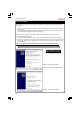
software installation Software installation After assembly of the circuit, it is now time to install the software drivers and examples and to test the VM140. Connect a 12V power supply (non regulated 12V adapter) to the power supply connector of the VM140 (SK2). The control LED LD12 (RUN) should light as well as LD13 to LD20 (these are the input control LEDs and light when the inputs are not active “LOW”). If OK, connect the USB connector of the VM140 to your PC using the included USB cable.
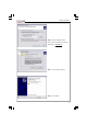
software installation Step 3 : Browse through the driver folder on your hard disk or included CD. Select driver : mchpusb.
software installation Installation is successful A utility to check the operation of the VM140 can be found in the “DIAG8061” subfolder. A more elaborate test application can be found in the “DEMO8061” subfolder. The source code of the test application can be found in the “DLL examples” subfolder. Explanation concerning the communication DLL of the VM140 can be found in the “DOC” subfolder.
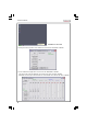
Connection example How to connect : Check the connections and respect limitations of the specifications to prevent damage. 2. Analog input : 1. Analog output : GND ! ANALOG OUTPUT VOLTAGE MAX 10V DC ! DAx : + GND 0 till 5V 0 ... 5V or 0 ... 10V OR 0 till 10V 3. Digital output : ADx : + 4. Digital input : +V Switch, ... +V :External power supply for relay, LED, Lamp.
Eigenschappen en technische gegevens Deze geassembleerde interfacekaart bestaat uit 33 ingangen / uitgangen, inclusief analoge / digitale en een PWM-uitgang. De aansluiting naar de computer is galvanisch-optisch geïsoleerd om beschadiging te vermijden en zo de implementering te beveiligen. Alle communicatieroutines zijn in een Dynamic Link Library (DLL) verzameld.
7 10 9 8 14 13 12 15 2 16 19 17 1 18 11 3 4 5 20 6 Aansluitingen Aansluitingen 11
aansluitingen 1 USB-connector Hier wordt de VM140 met de USB-poort van een pc verbonden. 2 12VDC Aansluiting van de voeding. Hier sluit men een 12V ongestabiliseerde adapter op aan die minimaal 300mA kan leveren.
software installatie Software installatie Na het opbouwen van de print is het nu tijd om de software drivers en voorbeelden te installeren en de VM140 te testen. Verbind een 12V voeding (ongestabiliseerde 12V adapter) met de VM140 voedingsconnector (SK2). De controle-LED LD12 (RUN) dient op te lichten alsook LD13 tot LD20 (dit zijn de controle-LEDs van de ingangen en lichten op als de ingangen niet actief “LAAG” zijn). Als dit o.k.
software installatie Stap 3 : Kies de gewenste locatie op je harde schijf selecteer driver : mchpusb.sys Stap 4 : Selecteer "Continue Anyway" om te bevestigen. Stap 5 : Selecteer "Finish" om de procedure te beëindigen.
software installatie Installatie is voltooid In de ‘DIAG8061’ subfolder vindt u een utility om de werking van de VM140 te controleren. In de ‘DEMO8061’ subfolder staat een uitgebreider testapplicatie. In de ‘DLL examples’ subfolder vindt u source code van de testapplicatie. In de ‘DOC’ subfolder vindt u uitleg over de communicatie-DLL van de VM140.
Aansluitvoorbeelden Hoe aansluiten? : Controleer alle verbindingen en respecteer de specificatielimieten om onherroepelijke schade te voorkomen. 1. Analoge uitgang 2. Analoge ingang : GND ! ANALOGE UITGANGSPANNING MAX 10V DC ! DAx : + GND 0 tot 5V 0 ... 5V of 0 ... 10V OF 0 tot 10V 3. Digitale uitgang : ADx : + 4. digitale ingang : +V Schakelaar, ...
Caractéristiques et données techniques Cette interface contient un total de 33 entées / sorties, y compris une sortie analogique / numérique + 1 sortie MLI. La connexion vers l'ordinateur est galvaniquement-optiquement isolée afin d'éviter les endommagements de l'ordinateur. De cette manière, une implémentation hautement sécurisée est assurée. Toutes les routines de communications sont rassemblées dans la Bibliothèque de Liaison Dynamique (DLL).
Points de connexion 7 10 9 8 14 13 12 15 2 16 19 17 1 18 11 3 4 5 6 20 Points de connexion 18
Points de connexion 1 Connexion USB Connexion de la VM140 au port USB d’un ordinateur. 2 12VCC Connexion de l’alimentation. Connectez un adaptateur 12V non régulé pouvant fournir un courant minimal de 300mA.
Installation du logiciel Installation du logiciel Après l’assemblage de la carte, il est maintenant temps d’installer les pilotes de logiciel et les exemples et de tester la VM140 Connectez une alimentation 12V (adaptateur 12V non régulé) au connecteur d’alimentation de la VM140 (SK2). La LED de contrôle LD12 (RUN) ainsi que LD13 à LD20 (les dernières sont les LEDs de contrôle des entrées et s’allument au cas où les entrées ne sont pas activement au niveau bas) doivent impérativement s’allumer.
Installation du logiciel Étape 3 : Feuilletez le dossier du pilote sur votre disque dur ou sur le CD inclus. Sélectionnez le pilote mchpusb.sys Étape 4: Sélectionnez "Continue Anyway" pour confirmer. Étape 5: Sélectionnez "Finish" pour compléter la procédure.
Installation du logiciel Installation complète Dans le sous-répertoire "DIAG8061" vous trouverez un fichier "utility" pour vérifier le fonctionnement de la VM140. Une application de test plus détaillée se trouve dans le sous-répertoire "DEMO8061". Dans le sous-répertoire "DLL examples" vous trouverez un code source de l’application de test. Dans le sous-répertoire ‘DOC’ vous trouverez l’explication concernant la DLL de communication de la VM140. .
Exemples de connexions Comment connecter ? Vérifiez toutes les connexions et respectez les limitations des spécifications afin d’éviter tout endommagement. 1. Sortie analogique: 2. Entrée analogique: GND TENSION DE SORTIE ANALOGIQUE ! MAX 10V DC ! DAx : + GND 0 à 5V 0 ... 5V ou 0 ... 10V Ou 0 à 10V 3. Sortie numérique: ADx : + 4. Entrée numérique: +V Interrupteur, ... +V :Alimentation externe pour relais, LED, lampe. ! MAX 50VDC OU GND Sortie collecteur ouvert du transistor externe.
Eigenschaften und Technische kenndaten Diese Schnittstelle hat insgesamt 33 Ein-/Ausgänge, mit analogem / digitalem und + 1PWM Ausgang. Der Anschluss an den Computer ist galvanisch-optisch isoliert, sodass Computerschaden nicht möglich ist und also ein hoher Sicherheitsgrad gewährleistet wird. Alle Kommunikationsroutinen sind in einer Dynamic Link Library (DLL) enthalten.
Anschlusspunkte 7 10 9 8 14 13 12 15 2 16 19 17 1 18 11 3 4 5 6 20 Anschlusspunkte 25
Anschlusspunkte 1 USB-Anschluss Hier können Sie die VM140 mit dem USB-Port eines PC anschließen. 2 12VDC Anschluss der Stromversorgung, hier müssen Sie einen 12V-nicht-stabilisierten Adapter, der mindestens 300mA liefern kann, anschließen.
Software-installation Software-installation Nach der Montage der Leiterplatte müssen Sie jetzt die Softwaretreiber und die Beispiele installieren und die VM140 testen. Verbinden Sie eine 12V-Stromversorgung (nicht-stabilisiertes 12V-Netzgerät) mit dem VM140 Stromversorgungsanschluss (SK2). Die Kontrollleuchte LED LD12 (RUN) sollte aufleuchten. LD13 bis LD20, das sind die Kontrollleuchten der Eingänge, leuchten auf wenn die Eingänge nicht aktiv, "NIEDRIG" sind.
Software-installation Schritt 3: Durchsuchen Sie den Treiberordner auf der Festplatte oder der mitgelieferten CD. Wählen Sie den Treiber aus mchpusb.sys Schritt 4: Wählen Sie "Continue anyway" zum Bestätigen Schritt 5: Wählen Sie "Finish" zum Beenden des Verfahrens.
Software-installation Installation beendet Im ‘DIAG8061’ Subfolder finden Sie ein Werkzeug um den Betrieb der VM140 zu überprüfen. Im DEMO8061’ Subfolder steht eine ausführlichere Testapplikation. Im ‘DLL examples’ Subfolder finden Sie den Quellencode der Testapplikation. Im ‘DOC’ Subfolder finden Sie mehr Information über die Kommunikations-DLL der VM140.
Anschlussbeispiele Wie anschließen? Überprüfen Sie alle Verbindungen und beachten Sie die Begrenzungen der technischen Daten, um Schaden zu vermeiden 1. Analoger Ausgang: 2. Analoger Eingang: GND ANALOGE AUSGANGSPANNUNG ! MAX 10V DC ! DAx : + GND 0 ... 5V 0 ... 5V oder 0 ... 10V ODER 0 ... 10V 3. Digitaler Ausgang: ADx : + 4. Digitaler Eingang: +V Schalter, ... +V :Externe Stromversorgun g für Relais, LED, Lampe.
Características & Especificaciones Esta interface consta de 33 entradas/salidas, incluso una salida analógica / digital y + 1 salida MLI. La conexión al ordenador está aislada de manera galvánica-óptica para evitar dañar el ordenador. Por tanto, se garantiza más seguridad. Una DLL - Dynamic Link Library (Biblioteca de vínculos dinámicos) contiene todas las rutinas de comunicación.
las puntas de conexión 7 10 9 8 14 13 12 15 2 16 19 17 1 18 11 3 4 5 6 20 Las puntas de conexión 32
las puntas de conexión 1 Conexión USB Conexión de la VM140 al puerto USB de un ordenador. 2 12VCC Conexión de la alimentación. Conecte un adaptador no estabilizado de 12V con una corriente mín. de 300mA.
Instalación del software Instalación del software Después de haber montado el CI puede instalar los drivers del software y los ejemplos y comprobar la VM140. Conecte una alimentación de 12V (adaptador 12V no estabilizado) al conector de alimentación VM140 (SK2). Tanto el LED de control LD12 (RUN) como los LEDs de LD13 a LD20 (son los LEDs de control de las entradas que se iluminarán si las entradas no están activas en el nivel “BAJO”) se iluminarán. Luego, conecte el cable USB (incl.
Instalación del software Paso 3: Hojee el fichero del driver en el disco duro o el CD incluido. Seleccione el driver mchpusb.sys Paso 4: Seleccione "Continue Anyway" para confirmar. Paso 5: Seleccione "Finish" para terminar el procedimiento.
Instalación del software Instalación terminada En el subdirectorio "DIAG8061" encontrará un fichero "utility" para verificar el funcionamiento de la K8061. Una aplicación de prueba más detallada está en el subdirectorio "DEMO8061".
Ejemplos de conexión ¿Cómo conectar? Verifique todas las conexiones y respete las limitaciones de las especificaciones para evitar cualquier daño. 1. Salida analógica: 2. Entrada analógica: GND TENSIÓN DE SALIDA ANALÓGICA ! MAX 10V DC ! DAx : + GND 0 ... 5V 0 ... 5V o 0 ... 10V O 0 ... 10V 3. Entrada digital: ADx : + 4. Salida digital: +V Interruptor, ... +V :Alimentación externa para relé, LED, lámpara.
Schematic diagram Schematic diagram 38
PCB PCB layout.
Extended USB interface board VM140 USER MANUAL Belgium [Head office] Velleman Components +32(0)9 384 36 11 France Velleman Electronique +33 320 15 86 15 Netherlands Velleman Components +31(0)76 514 7563 USA Velleman Inc.