VMB1LED PWM LED strip dimmer module for the Velbus system
CONTENTS CONTENTS .................................................................................................................... 2 DESCRIPTION................................................................................................................ 3 CHARACTERISTICS ...................................................................................................... 3 VELBUS CHARACTERISTICS ...................................................................................... 5 OVERVIEW ......
DESCRIPTION LED illumination is getting more popular. By dimming the output of the LED strips (12V or 24V series) an attractive atmosphere can be created. A dimmer module is placed between the external LED power supply and the LED strip. The use of Pulse Width Modulation (PWM) greatly reduces heat development inside the dimmer module compared to linear regulators. CHARACTERISTICS Dimmer: • Suitable for dimming 12 or 24V LED strips or low voltage lamps.
Led indications: • to show the dim position (0...
VELBUS CHARACTERISTICS • • • • • • 2-wire communication for Velbus data and 2 wires for power supply data transmission: 16.6 Kbit/s Serial data protocol: CAN (Controller Area Network) Short circuit proof (towards negative or positive pole of the power supply) bus error indication: 2 short flashes of the LEDs auto recovering after 25 seconds when a bus error occurs The dimmer module can be given a designation with a maximum of 16 characters.
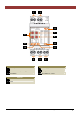
OVERVIEW 1 2 13 7 6 8 9 12 10 11 3 4 Wiring 5 LED indication 1 2 3 4 5 LED strip LED strip power supply Module or Velbus power supply Velbus Pushbutton 6 7 8 Address Mode Time 9 10 11 12 13 Power supply Receiving Velbus data Sending Velbus data Operating mode Dim position (0 ~ 100%) Settings VMB1LED PWM LED strip dimmer Manual– edition 1_rev.
LED INDICATION PWM LED: brightness indication for dim position On LED: on when input power supply is present Rx LED: on when receiving Velbus data Mode LED: • off when LED strip is off • on when LED strip lit with steady brightness • flashes fast while brighness of LED strip changes • flashes slow when switch-off delay is active • flashes very fast when dimmer module is in learning mode • flashes 2x short upon detecting a communication error Tx LED: on when transmitting Velbus data VMB1LED PWM LED str
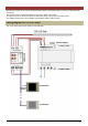
USE WITHOUT VELBUS The dimmer module can be used in combination with a direct current power supply (12 or 24V) to dim LED strips (12 or 24V). The function of the connected pushbuttons is set via the ‘Mode’ rotary switch. The switch-off time (or dim time in slowly on/off dimmer mode) is set via the ‘Time’ rotary switch. The address must be set to ‘00’ to disable communication with the Velbus system. Wiring diagram for 12V LED strips Use a 12V direct current power supply for the LED strips.
Wiring diagram for 24V LED strips Use a 24V direct current power supply for the LED strips. power supply pushbutton pushbutton VMB1LED PWM LED strip dimmer Manual– edition 1_rev.
Addressing When the Velbus is not used, the address must be set to ‘00’ to disable communication with the Velbus system. Remove the cover. Set both ‘ADDR’ rotary switches to ‘0’. ADDR = 00 VMB1LED PWM LED strip dimmer Manual– edition 1_rev.
Setting the operating mode The function of the pushbuttons is determined by the position of the ‘Mode’ and ‘Time’ rotary switches.
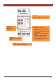
Depending on the setting of the ‘MODE’ rotary switch the dimmer module will act as follows: MODE 0 Operating mode Start/stop timer 1 Staircase lighting timer 2 Dimmer 3 Dimmer with memory function 4 Multiple position dimmer 5 Slowly on dimmer 6 Slowly off dimmer 7 Slowly on/off dimmer Description Pushing the pushbutton will switch on the LED strip. When the set time (see ‘TIME’ switch) expires the LED strip is switched off.
Depending on the ‘TIME’ rotary switch the time will be set as follows: TIME 0 1 2 3 4 5 6 7 8 9 A B C D E F Description Instant control (the LED strip lights up as soon as the pushbutton is pushed) 5 seconds switch-off time or 5 seconds dimming time in slowly on/off dim mode 10 seconds switch-off time or 10 seconds dimming time in slowly on/off dim mode 15 seconds switch-off time or 15 seconds dimming time in slowly on/off dim mode 30 seconds switch-off time or 30 seconds dimming time in slowly on/off dim
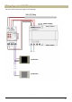
USE WITH A VELBUS SYSTEM The dimmer module can be part of a Velbus system and controlled by a control panel (VMB4PD) or using pushbuttons connected to a pushbutton interface (VMB8PB). To interconnect the Velbus modules the use of twisted-pair cable (EIB 2x2x0.8mm2, UTP 8x0.51mm - CAT5 or equivalent) is recommended. When a lot of modules (more than 10) are connected to the cable or longer cable lengths (more than 50m) are used, it is important to use a cable with appropriate diameter (0.5mm² or higher).
It is also possible to use the Velbus in combination with pushbuttons that are directly connected to the pushbutton input of the dimmer module. The function of the directly connected pushbuttons is set via the ‘Mode’ and ‘Time’ rotary switches. power supply pushbutton pushbutton VMB1LED PWM LED strip dimmer Manual– edition 1_rev.
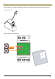
Wiring diagram for 24V LED strips Use a 24V direct current power supply for the LED strips. power supply A combination of the Velbus with directly connected pushbuttons is also possible. power supply pushbutton pushbutton VMB1LED PWM LED strip dimmer Manual– edition 1_rev.
Addressing Every module in the Velbus system must have a unique address. On modules with a rotary switch like this dimmer the address is set using the ‘ADDR’ rotary switch (also refer to the manual of the relevant module). For modules without rotary switches e.g. control panel VMB4PD or temperature controller VMB1TC the address is set via a menu (see manual of the VMB4PD or VMB1TC). These addresses may not be altered afterwards. Remove the cover.
Terminator Terminator Normally only 2 ‘TERM’ terminators must be used in a complete Velbus installation. Usually this will be on one module inside the distribution box and on the module which is physically located furthest from the distribution box. On all other modules, the terminator must be removed.
Operation The dimmer module can be operated in different ways: • using pushbuttons directly connected to the pushbutton input: o that activates the mode as set by the rotary switches (see ‘Use without Velbus’). • using pushbuttons connected to a Velbus via a pushbutton interface VMB8PB or control panel VMB4PD: o to switch on the LED strip (full brightness). o to switch off the LED strip. o to switch on (full brightness) or switch off the LED strip. o to activate the mode as set by the rotary switches.
In the following example a control panel VMB4PD is used from which 8 controls are linked to a dimmer module. • The upper and lower left buttons are used to create atmospheres that are used when watching television or reading a book. • The upper right button is used to increase LED strip brightness. • The lower right button is used to decrease LED strip brightness. On the second page: • the upper left button is used to change the brightness of the LED strip (dimming).
Linking switch-off pushbuttons With these pushbuttons the LED strip is switched off. In our example, we will use the lower right button on the second page of the control panel to switch off the LED strip. Remember the address of the dimmer module to reinstate it later on. Set the address of the dimmer module to ‘F1’. The MODE LED on the dimmer module and the indication LED(s) of the already linked switch-off pushbutton(s) will flash (fast).
Linking switch-on pushbuttons With these pushbuttons the LED strip is switched on to full brightness. In our example, we will use the upper right button on the second page of the control panel to switch on the LED strip to full brightness. Remember the address of the dimmer module to reinstate it later on. Set the address of the dimmer module to ‘E1’. The MODE LED on the dimmer module and the indication LED(s) of the already linked switch-on pushbutton(s) will flash (fast).
Linking switch-on/off pushbuttons With these pushbuttons the LED strip is switched on to full brightness. Once lit, another push on the pushbutton will switch the LED strip off. In our example, we will use the lower left button on the second page of the control panel to switch the LED strip on or off. Remember the address of the dimmer module to reinstate it later on. Set the address of the dimmer module to ‘D1’.
Linking dimming pushbuttons With these pushbuttons the LED strip can be dimmed. The function of the dimming push buttons is determined by the settings of the ‘Mode’ and ‘Time’ rotary switches (see § Setting the operating mode). In our example, we will use the upper left button on the second page of the control panel to dim the LED strip. Remember the address of the dimmer module to reinstate it later on. Set the address of the dimmer module to ‘C1’.
Linking pushbuttons to increase brightness Push and hold these pushbuttons will increase the brightness of the LED strip. A short press on these pushbuttons will light up the LED strip to full brightness. In our example, we will use the upper right button to increase the brightness of the LED strip. Remember the address of the dimmer module to reinstate it later on. Set the address of the dimmer module to ‘B1’.
Linking pushbuttons to decrease brightness Push and hold these pushbuttons will decrease the brightness of the LED strip. A short press on these pushbuttons will switch off the LED strip. In our example, we will use the lower right button to decrease the brightness of the LED strip. Remember the address of the dimmer module to reinstate it later on. Set the address of the dimmer module to ‘A1’.
Creating atmospheres These pushbuttons can be linked to a certain brightness to create different atmospheres. In this example we will use the upper left button of the control panel to create an ideal atmosphere for watching television (low brightness) while the lower left button will be used to create an atmosphere to read a book (high brightness). Remember the address of the dimmer module to reinstate it later on. First the atmosphere buttons must be linked. Set the address of the dimmer module to ‘91’.
Next step is to assign brightness levels to those atmosphere pushbuttons. Set the address of the dimmer module to ‘81’. The MODE LED on the dimmer module and the indication LED(s) of the already linked atmosphere pushbutton(s) will flash (fast). This way it can easily be determined which pushbuttons already have an atmosphere function assigned.
Set all atmospheres to maximum brightness Remember the address of the dimmer module to reinstate it later on. Set the address of the dimmer module to ‘81’. The MODE LED on the dimmer module will flash. To set all linked atmospheres to full brightness, press and hold the manual control on the dimmer module until the PWM LED lights up.
Deleting assigned pushbuttons Remember the address of the dimmer module to reinstate it later on. Set the address of the dimmer module to the function for which the pushbuttons must be deleted.
Deleting assigned pushbuttons for a certain function Remember the address of the dimmer module to reinstate it later on. Set the address of the dimmer module to the function for which the pushbuttons must be deleted.
Deleting all assigned pushbuttons Remember the address of the dimmer module to reinstate it later on. Set the address of the dimmer module to ‘F1’. The MODE LED on the dimmer module will flash (fast). Deleting all linked pushbuttons for all operating functions, press and hold the manual control on the dimmer module for 10 seconds. First the PWM LED on the dimmer module will light up and about 7 seconds later it will switch off again to confirm that all pushbuttons are deleted.
Setting the operating mode The function of the directly connected pushbuttons or linked ‘DIM’ Velbus pushbuttons is determined by the position of the ‘Mode’ and ‘Time’ rotary switches.
Depending on the setting of the ‘MODE’ rotary switch the directly connected pushbuttons or the learned ‘DIM’ Velbus pushbuttons will activate following function: MODE 0 Operating mode Start/stop timer 1 Staircase lighting timer 2 Dimmer 3 Dimmer with memory function 4 Multiple position dimmer 5 Slowly on dimmer 6 Slowly off dimmer 7 Slowly on/off dimmer Description Pushing the pushbutton will switch on the LED strip.
Depending on the ‘TIME’ rotary switch the time will be set as follows: TIME 0 1 2 3 4 5 6 7 8 9 A B C D E F Description Instant control (the LED strip lights up as soon as the pushbutton is pushed) 5 seconds switch-off time or 5 seconds dimming time in slowly on/off dim mode 10 seconds switch-off time or 10 seconds dimming time in slowly on/off dim mode 15 seconds switch-off time or 15 seconds dimming time in slowly on/off dim mode 30 seconds switch-off time or 30 seconds dimming time in slowly on/off dim
Software version verification The software version can be verified using the Velbus link program. Check http://www.velbus.eu whether you have the latest version. If a newer version is available, download it. Connect the Velbus interface to a PC and run the upgrade-software. Follow the instructions on the screen. Remark: Upgrading a module is not without risk. Do not interrupt the process! If for any reason the upgrade should fail, the module will cease normal operation.
VMB1LED PWM LED strip dimmer Manual– edition 1_rev.
Refer to our website for more information : www.velbus.be VMB1LED PWM LED strip dimmer Manual– edition 1_rev.