USER’S MANUAL AND PROGRAMMING GUIDE Firmware Version 4.07 HDL-64E S2 and S2.
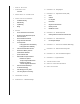
i SAFETY NOTICES 1 INTRODUCTION 16 A P P E N D I X B : Wiring Diagram 17 A P P E N D I X C : Digital Sensor Recorder (DSR) In The Box 2 3 P R I N C I P L E S O F O P E R AT I O N I N S TA L L AT I O N O V E R V I E W 17 Install 17 Calibrate 3 Front/Back Mounting 17 Live Playback 4 Side Mounting 18 Record Data 5 Top Mounting 18 Playback of Recorded Files 6 Wiring 19 DSR Key Controls 19 DSR Mouse Controls 6 USAGE 6 Use the Included Point-cloud Viewer 20 6 Develop Your Own
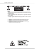
caution — safety notice Caution To reduce the risk of electric shock and to avoid violating the warranty, do not open sensor body. Refer servicing to qualified service personnel. The lightning flash with arrowhead symbol is intended to alert the user to the presence of uninsulated “dangerous voltage” within the product’s enclosure that may be of sufficient magnitude to constitute a risk of electric shock to persons.
introduction HDL-64E S2 and S2.1 User’s Manual Congratulations on your purchase of a Velodyne HDL-64E S2 or S2.1 High Definition LiDAR Sensor. These sensors represent a breakthrough in sensing technology by providing more information about the surrounding environment than previously possible. The HDL-64E S2 or S2.1 High Definition LiDAR sensors are referred to as the sensor throughout this manual.
P r i n c i P L e s o f o P e r at i o n HDL-64E S2 and S2.1 User’s Manual The sensor operates, instead of a single laser firing through a rotating mirror, with 64 lasers fixed mounted on upper and lower laser blocks, each housing 32 lasers. Both laser blocks rotate as a single unit. With this design each of the lasers fires tens of thousands of times per second, providing exponentially more data points/second and a more data-intensive point cloud than a rotating mirror design.
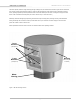
i n s ta L L at i o n o V e rV i e W HDL-64E S2 and S2.1 User’s Manual The sensor base provides the following mounting options: • Front/Back mount (Figure 2) • Side mount (Figure 3) • Top mount (Figure 4) The sensor can be mounted at any angle from 0 to 90° with respect to its base. Refer to Appendix A for complete dimensions. For all mounting options, mount the sensor to withstand vibration and shock without risk of detachment.
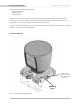
i n s ta L L at i o n o V e rV i e W HDL-64E S2 and S2.1 User’s Manual Side Mounting Mounting Base [152.4mm] 6.00 [203.2mm] 8.00 [21mm] [25.4mm] .83 1.00 Figure 3. Side HDL mounting illustration.
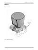
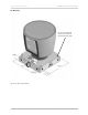
i n s ta L L at i o n o V e rV i e W HDL-64E S2 and S2.1 User’s Manual Top Mounting Four 0.41” [10.3mm] through holes for top mount option to secure the HDL to the vehicle. [33.8mm] 1.33 [177.8mm] 7.00 [177.8mm] 7.00 [12.7mm] .50 [12.7mm] .50 Figure 4. Top HDL mounting illustration.
i n s ta L L at i o n o V e rV i e W HDL-64E S2 and S2.1 User’s Manual Wiring The sensor comes with a pre-wired connector, wired with power, DB9 serial and standard RJ45 Ethernet connectors. The connector wires are approximately 10’ [3 meters] in length. Power. Connect the red and black wires to vehicle power. Be sure red is positive polarity. THE SENSOR IS RATED ONLY FOR 12 - 16 VOLTS. Any voltage applied over 16 volts could damage the sensor. The sensor draws 4-6 AMPS during normal usage.
usaGe HDL-64E S2 and S2.1 User’s Manual The following provides more detail on each of the above steps. 1. Establish communication with the sensor. The sensor broadcasts UDP packets. By using a network monitoring tool, such as Wireshark, you can capture and observe the packets as they are generated by the sensor. See Appendix E for the UDP packet format. The default source IP address for the sensor is 192.168.3.043, and the destination IP address is 192.168.3.255. To change these IP addresses, see page 11.
usaGe HDL-64E S2 and S2.1 User’s Manual 3. Parse the packets for rotation, block, distance and intensity data. Each sensor’s LIFO data packet has a 1206 byte payload consisting of 12 blocks of 100 byte firing data followed by 6 bytes of calibration and other information pertaining to the sensor. Each 100 byte record contains a block identifier, then a rotational value followed by 32 3-byte combinations that report on each laser fired for the block. Two bytes report distance to the nearest 0.
usaGe HDL-64E S2 and S2.
usaGe HDL-64E S2 and S2.1 User’s Manual Control Spin Rate Change Spin Rate in Flash Memory The sensor can spin at rates ranging from 300 RPM (5 Hz) to 1200 RPM (20 Hz). The default is 600 RPM (10 Hz). Changing the spin rate does not change the data rate – the unit sends out the same number of packets (at a rate of ~1.3 million data points per second) regardless of its spin rate. The horizontal image resolution increases or decreases depending on rotation speed.
usaGe HDL-64E S2 and S2.1 User’s Manual Define Sensor Memory IP Source and Destination Addresses The HDL-64E comes with the following default IP addresses: • Source: 192.168.3.043 • Destination: 192.168.3.255 To change either of the above IP addresses, issue a serial command of the case sensitive format #HDLIPAssssssssssssdddddddddddd$ where, • ssssssssssss is the source 12-digit IP address • dddddddddddd is the destination 12-digit IP address Use all 12 digits to set an IP address.
usaGe HDL-64E S2 and S2.1 User’s Manual The images below show the GPS adaptor box, included with the HDL-64E, and optional GPS receiver. GPS EQUIPMENT GPS Receiver Model No. HDL-64-GPS (Optional) GPS Adaptor Box Model No.
usaGe HDL-64E S2 and S2.1 User’s Manual Packet Format and Status Byte for GPS Time Stamping The 6 bytes at the end of the data packet report GPS timing and synchronization data. For every packet, the last 6 bytes are formatted as follows: Timestamp Bytes in Reverse Order in Microseconds Bytes 4 Description Notes GPS timestamp 32 bit unsigned integer timestamp. This value represents microseconds from the top of the hour to the first laser firing in the packet.
usaGe HDL-64E S2 and S2.1 User’s Manual Lasers are numbered sequentially starting with 0 for the first lower block laser to 31 for the last lower block laser; and 32 for the first upper block laser to 63 for the last upper block laser. For example, laser 32 fires simultaneously with laser 0, laser 33 fires with laser 1, and so on. The sensor has an equal number of upper and lower block returns.
[ 15 ] 1.70 43.2 10.24 260.2 8.00 203.2 4.50 114.3 6.00 152.4 CL 7.00 177.8 8.00 203.2 1.27 32.3 .83 21 TWO M8-1.25X12MM DEEP MOUNTING POINTS (2 PER SIDE FOR A TOTAL OF 8) 7.00 177.8 FOUR .41 [10.3] THRU FOR TOP MOUNT OPTION 8.80 223.5 .71 17.9 6.00 152.4 CL ISOMETRIC VIEW .83 21 1.93 49 a P P e n d i x a : M e c h a n i c a L d r aW i n G s HDL-64E S2 and S2.
Harting Technology Group Metal Version, Standard Straight Style Model No. 10-12-005-2001 aPPendix B: WirinG diaGraM HDL-64E S2 and S2.
a P P e n d i x c : d i G i ta L s e n s o r r e c o r d e r (dsr) HDL-64E S2 and S2.1 User’s Manual Digital Sensor Recorder (DSR) DSR is a 3D point-cloud visualization software program designed for use with the sensor. This software is an “out of the box” tool for the rendering and recording of point cloud data from the HDL unit. You can develop visualization software using the DSR as a reference platform.
a P P e n d i x c : d i G i ta L s e n s o r r e c o r d er (dsr) HDL-64E S2 and S2.1 User’s Manual Record Data 1. Confirm the input of streaming data through the live playback feature. 2. Click the Record button. RECORD button = 5. Enter the name and location for the pcap file to be created. 6. Recording begins immediately once the file information has been entered. 7. Click Record again to discontinue the capture. 8.
a P P e n d i x c : d i G i ta L s e n s o r r e c o r d er (dsr) HDL-64E S2 and S2.1 User’s Manual DSR Key Controls Zoom: Z = Zoom in Shift, Z = Zoom out Z Axis Rotation: Y = Rotate CW Shift, Y = Rotate CCW X Axis Rotation: P = Rotate CW Shift, P = Rotate CCW Y Axis Rotation: R = Rotate CW Shift, R = Rotate CCW Z Shift: F = Forward B = Back X Shift: L = Left H = Right Y Shift: U = Up D = Down Aux.
a P P e n d i x d : M at L a B s a M P L e c o d e HDL-64E S2 and S2.1 User’s Manual Matlab sample code to read calibration data from HDL-64E output. fileFilter = '*.pcap'; [File_name,Directory]=uigetfile(fileFilter,'Open a .pcap file') ; Filename=[Directory File_name]; tic; fid=fopen(Filename); ttc=fread(fid,40); ttc=fread(fid,42); ttc=fread(fid,inf,'1206*uint8=>uint8',58); %ttch=dec2hex(ttc); % Determine how many data packets. Packet=size(ttc)/1206; % Convert data to single precision.
a P P e n d i x d : M at L a B s a M P L e c o d e HDL-64E S2 and S2.1 User’s Manual % Add high and low bytes of Rotational Correction Factor together and check if positive or negative correction factor. RotationalCorr(i)=temp(5)*256+temp(4); if RotationalCorr(i)>32768 RotationalCorr(i)=RotationalCorr(i)-65536; End % Scale Rotational Correction Factor by Diving by 100.
a P P e n d i x d : M at L a B s a M P L e c o d e HDL-64E S2 and S2.1 User’s Manual Version=dec2hex(value(s-1)) Temperature=value(s-2) GPS=value(s-3) speed=single(value(s-48))+single(value(s-47))*256 Fov_start=single(value(s-46))+single(value(s-45))*256 Fov_end=single(value(s-44))+single(value(s-43))*256 warning=value(s-13) power=value(s-12) Humidity=value(s-58) % Done with Unit Parameters. Reading Calibration and Sensor Parameter Data Laser ID # is a 1 byte integer.
a P P e n d i x e : d ata Pa c K e t f o r M at HDL-64E S2 and S2.1 User’s Manual Data Packet Format The sensor outputs UDP Ethernet packets. Each packet contains a header, a data payload of firing data and status data. Data packets are assembled with the collection of all firing data for six upper block sequences and six lower block sequences. The upper block laser distance and intensity data is collected first followed by the lower block laser data.
a P P e n d i x e : d ata Pa c K e t f o r M at HDL-64E S2 and S2.1 User’s Manual Firmware version 4.07 (sheet 1 of 3) 47 Version 4.
a P P e n d i x e : d ata Pa c K e t f o r M at HDL-64E S2 and S2.1 User’s Manual Firmware version 4.07 (sheet 2 of 3) Reserved* Reserved* Reserved* Reserved* Reserved* Reserved* Upper Block Threshold FE Lower Block Threshold FF *For Laser 63, these bytes will contain the time stamp representing when the calibration data was uploaded in the following sequence: [ 25 ] * Year * Month * Day * Hour * Min * Sec.
a P P e n d i x e : d ata Pa c K e t f o r M at HDL-64E S2 and S2.1 User’s Manual Firmware version 4.
a P P e n d i x e : d ata Pa c K e t f o r M at HDL-64E S2 and S2.1 User’s Manual Last Six Bytes Examples Examples of the last row of 11 consecutive packets follows. In all cases, the “seconds” figure represents the origin of the packet expressed in seconds since the top of the hour.
a P P e n d i x e : d ata Pa c K e t f o r M at HDL-64E S2 and S2.1 User’s Manual PACKET #7652: PACKET #7653: PACKET #7654: PACKET #7655: PACKET #7656: 47 40 = Ver 4.
a P P e n d i x e : d ata Pa c K e t f o r M at HDL-64E S2 and S2.
a P P e n d i x f : d u a L t W o P o i n t c a L i B r ation MethodoLoGy HDL-64E S2 and S2.1 User’s Manual Dual Two Point Calibration Methodology and Code Samples Velodyne uses a dual point calibration methodology to calculate the values in the db.xml file. This section describes this calibration methodology. The steps for the calibration are as follows: 1: Perform far point calibration at 25.04m 2: Perform near point X calibration at 2.4m 3: Perform near point Y calibration at 1.
a P P e n d i x f : d u a L t W o P o i n t c a L i B r ation MethodoLoGy HDL-64E S2 and S2.
a P P e n d i x f : d u a L t W o P o i n t c a L i B r ation MethodoLoGy HDL-64E S2 and S2.1 User’s Manual Intensity Compensation vs Distance Intensity compensation is done in the software for different channels by changing a parameter in the calibration window until the measurement gets to a uniform intensity for a reference target.
a P P e n d i x f : d u a L t W o P o i n t c a L i B r ation MethodoLoGy HDL-64E S2 and S2.
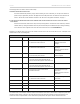
a P P e n d i x G : e t h e r n e t t r a n s i t t i M i n G taBLe HDL-64E S2 and S2.1 User’s Manual HDL-64E Ethernet Timing Table Overview The Ethernet Timing Table shows how much time elapses between the actual capturing of a point’s data event and when that point is an event output from the sensor. By registering the event of the Ethernet data capture, you can calculate back in time the exact time at which any particular distance point was captured.
Laser Block Upper Lower Upper Lower Upper Lower Upper Lower Upper Lower Upper Lower Data Block 1 2 3 4 5 6 7 8 9 10 11 12 Laser Block Upper Lower Upper Lower Upper Lower Upper Lower Upper Lower Upper Lower Data Block 1 2 3 4 5 6 7 8 9 10 11 12 16,48 407.65 407.65 384.36 384.36 361.06 361.06 337.76 337.76 314.47 314.47 291.17 291.17 0,32 419.30 419.30 396.00 396.00 372.71 372.71 349.41 349.41 326.12 326.12 302.82 302.82 2,34 417.84 417.84 394.55 394.55 371.25 371.25 347.96 347.96 324.66 324.66 301.
a P P e n d i x h : L a s e r a n d d e t e c to r a r ranGeMent SENSOR AS SEEN FROM THE BACK OF THE UNIT SENSOR BEAM ON THE WALL AS SEEN ON CAMERA IN NIGHT VISION MODE [ 36 ] HDL-64E S2 and S2.
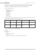
aPPendix i: anGuLar resoLution HDL-64E S2 and S2.1 User’s Manual RPM RPS (Hz) Total Laser Points per Revolution Points Per Laser per Revolution Angular Resolution (degrees) 300 5 266,627 4167 .0864 600 10 133,333 2083 .1728 900 15 88,889 1389 .2592 1200 20 66,667 1042 .3456 notes: These values apply equally to the upper and lower block.
trouBLeshootinG HDL-64E S2 and S2.1 User’s Manual Use this chart to troubleshoot common problems with the sensor.Use this chart to troubleshoot common problems with the sensor. Problem Resolution Unit doesn’t spin Verify power connection and polarity. Verify proper voltage – should be 16 volts drawing about 3-4 amps. Remove bottom cover and check inline 10 amp fuse. Replace if necessary. Model No. ATM-10. Unit spins but no data Verify Ethernet wiring. Verify packet output with another tool (e.g.
s P e c i f i c at i o n s Sensor: HDL-64E S2 and S2.1 User’s Manual • 64 lasers/detectors • 360 degree field of view (azimuth) • 0.09 degree angular resolution (azimuth) • Vertical Field of View: S2: +2 — -8.33 @ 1/3 degree spacing -8.83 — -24.33 @ 1/2 degree spacing S2.1: +2 — -29.5 @ 1/2 degree spacing • <2cm distance accuracy (one sigma) • 5-20 Hz field of view update (user selectable) • 50 meter range for pavement (~0.10 reflectivity) • 120 meter range for cars and foliage (~0.
Velodyne LiDAR, Inc. 345 Digital Drive Morgan Hill, CA 95037 408.465.2800 voice 408.779.9227 fax 408.779.9208 service fax www.velodynelidar.com Service Email: lidarservice@velodyne.com Product Email: help@velodyne.com Technical Email: lidarhelp@velodyne.com Sales Email: lidar@velodyne.com All Velodyne products are made in the U.S.A. Specifications subject to change without notice Other trademarks or registered trademarks are property of their respective owner.