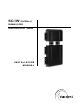
SC-IW (In-Wall) Subwoofer SubContractorTM Series INSTALLATION MANUAL
Caution! . www.velodyne.
At t e n t i o n ! . www.velodyne.
Vo r s i c h t ! . www.velodyne.
At t e n z i o n e ! . www.velodyne.
Ta b l e o f C o n t e n t s Product Overview.................................................................................................1 - Driver Technology ...........................................................................................1 - Cabinet Technology .........................................................................................1 Installation Overview .............................................................................................
Product Ov ervie w The SC-IW (In-Wall) subwoofer can be installed in a variety of locations and positions in any given installation. Although this product is extremely versatile and flexible in its uses, it has been specifically designed for two major applications - New Construction Installations and Retro-Fit Installations in structures made of traditional 2x4 studs with 16 inch spacing, on-center. This document provides the detailed process for properly installing the SC-IW into a wall.
The SC-IW consists of two cabinets — the “driver module” and the “back box.” (a.k.a. the “Enclosure”). Unlike other in-wall products where a back box may be optional, the SC-IW requires both enclosures, unaltered, for every installation. In new construction situations, the back box is in installed first (for example, at the framing or rough out stage), and the driver module is installed later in the trim out stage. In retrofit situations both boxes are typically installed together.
The SC-IW comes in two completely separate cartons — the SC-IWBB (Back Box) and the SC-IWDVR (Driver).
New Construction Installation — Standard Grille Note: This installation process assumes that the installer has access to the open framed 2x4 studded wall with 16 inch spacing. In the event that the stud spacing is larger, an additional 2x4 or other spacer can be used to fill the space between the SC-IW back box and the neighboring stud. Step 1 - Install Mudring Unpack the first carton (SC-IWBB) and place the contents on the floor. Remove the mudring from the packaging.
Step 2 - Install Back Box Once the mudring is stapled into place, the back box should be installed using eight of the phillips drive flat head screws included in the package. When installing the back box, the mudring should be aligned to the white line on the cabinet. Once the mudring and the back box are aligned, install the back box as shown. Figure 2: Install Back Box . www.velodyne.
Step 3 - Route Wire Route the wire from the location where the electronics gear is located to where the SC-IW will be. There is "extra space" between the studs and the back box in the event that the wire has to pass along the side of the back box to the driver module.
Step 5 - Finish Wall The wall can now be finished in a traditional fashion utilizing the appropriate drywall thickness, standard texturing and finishing methods. Be sure to advise the "finishing” contractors that they are to drywall up to the edge of the mudring, as the mudring is the place holder for the installation of the driver module and standard grille. Figure 4: Finish Wall Note: Steps 6 through 14 presume that you have obtained and are ready to install the SC-IWDVR (In-Wall Driver Module).
Step 7 - Remove Mudring At this point, the mudring can be removed. It should be easily removed by "pulling it through" the drywall opening. After it is removed, discard. Figure 5: Remove Mudring . www.velodyne.
Step 8 - Place Clamp Rings on Driver Module Remove the two clamp rings from the packaging and place a clamp ring onto each of the bottom edges of the tubes. Note: The position of the clamp ring is critical. Make sure that the screw section of the ring is on either side of the tube and not on the front or the back. Please see picture below. Screw must face outward Figure 6: Clamp Ring Placement . www.velodyne.
Step 9 - Install Driver Module Insert the driver module assembly through the opening left in the wall by the mudring and slide the plastic tubes onto the two connection tubes The connection tubes should slide all the way down onto the surface of the driver module assembly. Once the tubes are flush with the driver module, firmly tighten the two clamp rings to seal the rubber coupling to the plastic tube.
Step 10 - Remove Metal Grille Obtain the standard grille with integrated scoop and remove the metal grille insert, as shown, in the picture below. Figure 8: Metal Grille Insert Removal Note: The grille can be painted to match the de´cor. The supplied paint mask can be used to paint the grille frame while the metal grille insert can be painted separately. . www.velodyne.
Step 11 - Install Grille Frame Install the plastic grille onto the driver module using the four included machine screws. The grille hardware should easily be installed into the side of the cabinet. Tighten using the supplied allen wrench. Figure 9: Grille Frame Installation . www.velodyne.
Step 12 - Secure Grille Install two pan head phillips screws (provided) into standard grille into bottom left and bottom right holes. Figure 10: Secure Grille . www.velodyne.
Step 13 - Install Metal Grille Insert Figure 11: Metal Grille Insert Installation Step 14 - Installation Complete The installation is complete. Test the installation with bass audio material and check for buzzes, rattles, and air leaks and address accordingly. Figure 12: Completed Installation . www.velodyne.
New Construction Installation — Designer Grille Note: This installation process assumes that the installer has access to the open framed 2x4 studded wall with 16 inch spacing. (In the event that the stud spacing is larger, an additional 2x4 or other spacer can be used to fill the space between the SC-IW back box and the neighboring stud.) Step 1 - Assemble Cabinet and Driver Modules Together Remove both the back box and driver modules from the packaging and place them on a clean surface.
Step 2 - Mark Installation Location Measure from the bottom (or top if the SC-IW is to fire upwards) of the designer grille’s lowest (or highest) position 6 3/8” up along the stud and mark the stud in this location. This location will determine the bottom edge of the bracket on the driver module. 6 3/8” Figure 14: Mark Installation Location . www.velodyne.
Step 3 - Route Wire Route the wire from the location where the electronics gear is located to where the SC-IW will be. There is "extra space" between the studs and the back box in the event that the wire has to pass along the side of the back box to the driver module. Figure 15: Route Wire . www.velodyne.
Step 4 - Secure Subwoofer to Wall After the location has been determined, securely fasten the subwoofer to the studs. Velodyne provides 12 screws for this purpose. Figure 16: Secure Subwoofer . www.velodyne.
Step 5 - Connect Speaker Wire to Subwoofer Connect the previously routed speaker wire to the subwoofer taking care to match the positive wire to the red terminal and the negative wire to the black terminal. The spring loaded binding post will hold and secure the wire in place. Figure 17: Speaker Wire Installation . www.velodyne.
Step 6 - Install Filler Panel Velodyne provides an MDF filler panel to fill the distance between the driver module and the drywall. This filler panel also acts as a guide for the standard grille. The filler panel easily installs using the four flat head screws and included allen wrench. Be sure to orientate the filler panel as shown such that the tapered edge faces way from the driver. Tapered Edge Tapered Edge Tapered Edge Straight Edge Figure 18: Filler Panel Installation . www.velodyne.
Step 7 - Install Template Place Holder Cut out the part of the installation template that outlines the designer grille. Affix the template to the studs at the bottom of the filler panel as shown. Figure 19: Template Place Holder Installation . www.velodyne.
Step 8 - Finish Wall The wall can now be finished in a traditional fashion utilizing the appropriate drywall thickness, standard texturing and finishing methods. Be sure to advise the "finishing” contractors that they are to drywall up to the edge of the template, as the template is the place holder for the installation of the designer template grille.
Step 10 - Install Designer Grille Remove metal grille insert from the plastic grille and insert into opening into the wall. The grille should then be affixed to the studs using the four included phillips drive pan head screws. Figures 21a and 21b: Designer Grille Installation . www.velodyne.
Step 11 - Install Metal Insert into Plastic Grille Frame Figure 22: Metal Insert Installation Step 12 - Finished Grille . Figure 23: Finished Grille Installation www.velodyne.
R e t r o - F i t I n s ta l l a t i o n w i t h D e s i g n e r G r i l l e Step 1 - Decide on Subwoofer Orientation and Grille Location The first decision for a retrofit installation is which way the subwoofer will face (up or down), and therefore where the designer grille will be located on the wall (near the floor or ceiling). Once the location is decided, locate the 2x4 studs, spaced 16 inches on center.
Step 2 - Cut Out Drywall Per Template Once the studs have been located, place the supplied designer grille template on the wall. After the template is secured to the wall with either staples or tape, score the drywall along the lines as detailed on the template. Figure 25: Cut Out Drywall Per Template Note: Two templates are provided, one for the designer grille and one for the standard grille. Be sure to use the correct template! . www.velodyne.
Step 3 - Remove Drywall After it is Scored After the drywall is scored, remove the template and the drywall as indicated. The cutout after removal is shown in figures 26a and 26b. Figures 26a and 26b: Drywall Removal . www.velodyne.
Step 4 - Run Speaker Wire from Amplifier Location to In-Wall Subwoofer Route the wire from the location where the electronics gear is located to where the SC-IW will be. There is extra space between the studs and the box in the event that the wire has to pass along the side of the back box to the driver module. Figure 27: Speaker Wire Installation Note: 14 AWG or larger wire is recommended. . www.velodyne.
Step 5 - Assemble Cabinet and Driver Modules Together Remove both the back box and driver modules from the packaging and place them on a clean surface. Place the back box with the two silicon rubber tubes facing upward. Remove the two clamp rings from the packaging and place them over the tubes. Figures 28a and 28b: Cabinet and Driver Module Assembly . Note: Leave the paint cover on the driver to prevent damage during the installation, painting and finishing process. www.velodyne.
Step 6 - Mark Installation Location Measure from the bottom of the cutout 6 3/8” up along the stud and mark the stud in this location. This location will determine the bottom edge of the bracket on the driver module. 6 3/8” Figure 29: Mark Installation Location . www.velodyne.
Step 7 - Install Subwoofer into Opening After the in-wall subwoofer assembly is complete, and the mounting position marked, orient the assembly inside the wall. In this installation example we have decided to face the unit downward. It is critical at this point that the top of the cabinet module is aligned with the top of the cutout and that the brackets are 6 3/8” from the bottom of the cutout. 6 3/8” Figure 30: Subwoofer Installation . www.velodyne.
Step 8 - Secure Subwoofer to Wall After the location has been determined, securely fasten the subwoofer to the studs. Velodyne provides 12 screws for this purpose. Figure 31: Secure Subwoofer . www.velodyne.
Step 9 - Connect Speaker Wire to Subwoofer Connect the previously routed speaker wire to the subwoofer taking care to match the positive wire to the red terminal and the negative wire to the black terminal. The spring loaded binding post will hold and secure the wire in place. Figure 32: Connect Speaker Wire . www.velodyne.
Step 10 - Install Filler Panel Velodyne provides an MDF filler panel to fill the distance between the driver module and the drywall. This filler panel also acts as a guide for the designer grille. The filler panel easily installs using the four flat head screws and included allen wrench. Be sure to orientate the filler panel as shown such that the tapered edge faces way from the driver. Tapered Edge Tapered Edge Tapered Edge Straight Edge Figure 33: Filler Panel Installation . www.velodyne.
Step 11 - Install Drywall Above Filler Plate After the filler plate is secured to the driver module, install a replacement piece of drywall above the filler plate in the opening. This drywall should be securely fastened to the studs using drywall screws. Figure 34: Drywall Installation Step 12 - Tape, Mud, Texture and Paint Wall After the SC--IW is installed into the wall, the wall should be taped, textured, blended and then painted to match the existing wall.
Step 13 - Install Designer Grille Remove metal grille insert from the plastic grille and insert into opening into the wall. The grille should then be affixed to the studs using the four included phillips drive pan head screws. Figures 35a and 35b: Designer Grille Installation . www.velodyne.
Step 14 - Install Metal Insert into Plastic Grille Frame Figure 36: Metal Insert Installation Step 15 - Finished Grille . Figure 37: Finished Grille Installation www.velodyne.
R e t r o - F i t I n s ta l l a t i o n w i t h S ta n d a r d G r i l l e Step 1 - Decide on Subwoofer Orientation and Grille Location The first decision for a retrofit installation is which way the subwoofer will face (up or down), and therefore where the standard grille will be located on the wall (near the floor or ceiling). Once the location is decided, locate the 2x4 studs, spaced 16 inches on center.
Step 2 - Cut Out Drywall Per Template Once the studs have been located, place the supplied standard grille template on the wall. After the template is secured to the wall with either staples or tape, score the drywall along the lines as detailed on the template. Figure 39: Cut Out Drywall Note: Two templates are provided, one for the designer grille and one for the standard grille. Be sure to use the correct template! . www.velodyne.
Step 3 - Remove Drywall After it is Scored After the drywall is scored, remove the template and the drywall as indicated. The cutout after removal is shown in figures 40a and 40b. Figures 40a and 40b: Drywall Removal . www.velodyne.
Step 4 - Run Speaker Wire from Amplifier Location to In-Wall Subwoofer Route the wire from the location where the electronics gear is located to where the SC-IW will be. There is extra space between the studs and the box in the event that the wire has to pass along the side of the back box to the driver module. Figure 41: Speaker Wire Installation . www.velodyne.
Step 5 - Assemble Cabinet and Driver Modules Together Remove both the back box and driver modules from the packaging and place them on a clean surface. Place the back box with the two silicon rubber tubes facing upward. Remove the two clamp rings from the packaging and place them over the tubes. Figures 42a and 42b: Cabinet and Driver Module Assembly . Note: Leave the paint cover on the driver to prevent damage during the installation, painting and finishing process. www.velodyne.
Step 6 - Mark Installation Location Measure from the bottom of the cutout 5 3/8” up along the stud and mark the stud in this location. This location will determine the bottom edge of the bracket on the driver module. 5 3/8” Figure 43: Mark Installation Location . www.velodyne.
Step 7 - Install Subwoofer into Opening After the in-wall subwoofer assembly is complete, orientate the assembly inside the wall. In this installation example we have decided to face the unit downward. It is critical at this point that the top of the cabinet module is aligned with the top of the cutout and that the brackets are 5 3/8” from the bottom of the cutout. 5 3/8” Figure 44: Subwoofer Installation . www.velodyne.
Step 8 - Secure Subwoofer to Wall After the location has been determined, securely fasten the subwoofer to the studs. Velodyne provides 12 screws for this purpose. Figure 45: Secure Subwoofer . www.velodyne.
Step 9 - Connect Speaker Wire to Subwoofer Connect the previously routed speaker wire to the subwoofer taking care to match the positive wire to the red terminal and the negative wire to the black terminal. The spring loaded binding post will hold and secure the wire in place. Figure 46: Speaker Wire Installation . www.velodyne.
Step 10 - Install Filler Panel Velodyne provides an MDF filler panel to fill the distance between the driver module and the drywall. This filler panel also acts as a guide for the standard grille. The filler panel easily installs using the four flat head screws and included allen wrench. Be sure to orientate the filler panel as shown such that the tapered edge faces way from the driver. Tapered Edge Tapered Edge Tapered Edge Straight Edge Figure 47: Filler Panel Installation . www.velodyne.
Step 11 - Install Drywall Above Filler Plate After the filler plate is secured to the driver module, install a replacement piece of drywall above the filler plate in the opening. This drywall should be securely fastened to the studs using drywall screws. Figure 48: Drywall Installation Step 12 - Tape, Mud, Texture and Paint Wall After the Velodyne subwoofer is installed into the wall, the wall should be taped, textured, blended and then painted to match the existing wall.
Step 13 - Remove Metal Grille Remove the filler plate. Obtain the standard grille with integrated scoop and remove metal grille insert, as shown, in the picture below. Figure 49: Metal Grille Insert Removal . www.velodyne.
Step 14 - Install Grille Frame Install the plastic grille onto the driver module using the four included machine screws. The grille hardware should easily be installed into the side of the cabinet. Tighten using the supplied allen wrench. Figure 50: Grille Frame Installation . www.velodyne.
Step 15 - Secure Grille Install two pan head phillips screws (provided) into standard grille into bottom left and bottom right holes. Figure 51: Secure Grille . www.velodyne.
Step 16 - Install Metal Grille Insert Figure 52: Metal Grille Insert Installation Step 17 - Installation Complete The installation is complete. Test the installation with bass audio material and check for buzzes, rattles, and air leaks and address accordingly. The grille can also be painted to match the de´cor if desired. Figure 53: Completed Installation . www.velodyne.
Other Velodyne Subwoofer Products 110V DD Series DD-10 DD-12 DD-15 DD-18 Digital Drive 1812 Signature Edition DLS-R Series DLS-3500R DLS-3750R DLS-4000R DLS-5000R DPS Series DPS-10 DPS-12 . www.velodyne.
LIMITED WARRANTY VELODYNE ACOUSTICS, Inc. (“VELODYNE”) warrants all electronics and powered subwoofers for a period of two years and full range speakers for a period of five years. All VELODYNE products have a warranty from the date of purchase against defects in materials and workmanship subject to the following conditions: 1.