
Specifications


Starfire Series Manual
www.chrysalisacoustics.com
5
R EAR PANEL C ONNECTIONS
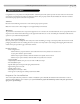
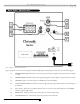
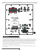
Figure 1. Starfire-10 and -12 Rear Panel Connections
Figure 1 shows the connections on the rear panel of the Starfire. Following are brief descriptions of the connections described in Figure 1.
(1) SPEAKER LEVEL INPUT terminals - Connect these input terminals to the speaker output terminals of your amplifier
or receiver.
(2) SPEAKER LEVEL OUTPUT terminals - The speaker-level signal to the front speakers is output from these terminals.
(3)
LI
N
E I
N
PUT jacks - Connect these jacks to the LINE OUT jacks of the amplifier.
(4) LOW-PASS CROSSOVER - Use this knob to select the high-frequency range at which you wish to cut-off the signal to
t
h
e s
u
b
w
oofer.
(5) Power indicator - Red: Unit is in standby mode. Green: Unit is in operation mode. (automatically turns to STANDBY
m
o
d
e i
f
n
o signal for eight minutes)
(6) PHASE switch - Select the switch position at which you hear a louder mid-bass sound.
(7) VOLUME LEVEL knob - Use this knob to adjust the output level of the subwoofer.