USER’S MANUAL SERIES Featuring Software Version 2.2.
Enjoy. Thank you for choosing a Velodyne. Our passion for high performance, low-distortion bass is the driving force behind our worldwide reputation in audio and technical innovation. We are pleased to bring the Velodyne sound experience to your home.
www.velodyne.
TABLE OF CONTENTS Congratulations. . . . . . . . . . . . . . . . . . . . . . . . . . . . . . . . . . . . . . . . . . . . . . . . . . . . . . . . . 1 Before you Begin . . . . . . . . . . . . . . . . . . . . . . . . . . . . . . . . . . . . . . . . . . . . . . . . . . . . . . . 1 Package Contents. . . . . . . . . . . . . . . . . . . . . . . . . . . . . . . . . . . . . . . . . . . . . . . . . . . . . . . 2 Product Features and Controls. . . . . . . . . . . . . . . . . . . . . . . . . . . . . . . . . . . . . . .
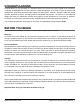
CONGRATULATIONS Congratulations on your purchase of a Velodyne Digital Drive subwoofer system! Digital Drive technology, universally acknowledged as the state-of-the-art in bass reproduction, is the result of years of research and development, combining advanced Digital Signal Processing (DSP), software, equalizer, audio filter, digital amplifier, digital servo control, and high-pressure loudspeaker technologies.
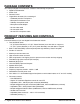
Package Contents Your Velodyne Digital Drive Subwoofer consists of the following components: • Digital Drive Subwoofer • Power Cord • Remote Control • Digital Drive Accessory Kit, consisting of: - Calibrated precision microphone - Microphone windscreen cover - Tabletop microphone stand - Microphone stand adapter - 25-foot video cable - 25-foot audio cable - 20-foot XLR microphone cable Product Features and Controls SUBWOOFER Prominent features of your new Digital Drive Subwoofer include: • Cone and Motor
- Theater/Music selection indicator (servo gain control) Signal sensing auto turn on/off/12 Volt trigger (defeatable) 6 presets for customized listening modes and EQ defeat Selectable default preset Switchable Velodyne logo indicator Night Mode maximum volume setting Save settings indicator Daisy chain feature REMOTE CONTROL The Velodyne Digital Drive infrared remote control allows you to set up, adjust, and reset your subwoofer when connected to a television or a video monitor.
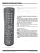
REMOTE CONTROL BUTTONS A brief description of each button on the remote control follows: • • • • • • • • • • • • • PWR – Causes woofer to stand by if in “Active” standby mode. NUMERIC KEYPAD – Used to enter SETUP modeand for other functions. SET (+/-) – Increases or decreases the Q valuefor a parametric EQ, or sets values on the settings page. LIGHT – Turns the subwoofer’s front panel Velodyne logo indicator on or off.
DIGITAL DRIVE ACCESSORY KIT The Velodyne Digital Drive Accessory Kit contains the following six components: • Calibrated precision microphone • Microphone windscreen cover • Tabletop microphone stand • Microphone stand adapter • 25-foot video cable • 25-foot audio cable • 20-foot XLR microphone cable Installation Overview Your new Velodyne servo subwoofer provides for a number of installation options.
Figure 2: Digital Drive Rear Panel Connections (1) POWER – Press the POWER switch to the ON position to activate the subwoofer. If the unit is to be left unused for an extended period of time, move this switch to the OFF position to prolong the life of the subwoofer. (2) POWER RECEPTACLE – Connect your detachable AC power plug to this male interface connection. The detachable cord allows for easy replacement should the original be damaged.
(6) LFE INPUT – This XLR input jack receives the balanced LFE signal from your receiver or processor. (7) MIC INPUT – This XLR input jack is for your XLR microphone cable. (8) EQ OUTPUT LEFT/RIGHT – Connect the audio cable from your accessory kit to these jacks: white plug to LEFT, and red plug to RIGHT. (9) THRU – These RCA connectors are for sharing the same signal that goes into your subwoofer with a second “daisy-chained” subwoofer. RCA input comes out of the THRU jack.
Installation – Quick Start To set up and take advantage of the EQ features in your new Digital Drive subwoofer in the least amount of time, perform the following steps: 1. Unpack the subwoofer and connect the power cable. 2. Connect an LFE input cable from your receiver/processor to the input jack. For other hookup options, see step 2, on the following page. 3. Power up the unit and ensure that it is receiving signal from your receiver (i.e. playing bass). 4.
Installation – Step-by-Step To ensure a quick and flawless installation of your Velodyne Digital Drive unit, follow these numbered setup instructions in their exact order. SUBWOOFER CABLE CONNECTIONS Make all necessary cable connections between the applicable subwoofer connector port and your particular home electronics equipment in the following order: 1. Insert the detachable AC power cord into the 117V~, 60Hz, 15A power interface port on the rear panel of your subwoofer.
4. Referring to Figure 2, Locations 5 and 8, connect the audio/video cable between your subwoofer (EQ OUTPUT VIDEO/LEFT/RIGHT yellow, white, and red respectively) and your electronics (receiver, processor, TV, etc.). Insert the color-coded cable plugs into the correct EQ OUTPUT receptacle – the yellow plug into the VIDEO jack, the white plug into the LEFT jack, and the red plug into the RIGHT jack. The opposite ends of this cable should be connected to your receiver/processor.
NOTE: When a DD subwoofer detects an incoming RS-232 command, it reverts to “Slave Mode.” This means that the subwoofer will no longer accept IR commands. To reestablish normal operations, remove the RS-232 cable and power cycle the unit. Note that the daisy chain connection ONLY allows the woofers to communicate basic “run-time” commands such as volume and preset. We recommend the following sequence when setting up daisy-chained subs. 1. First, connect only the master sub to the system.
Subwoofer setup – Overview BEFORE YOU BEGIN: Once the installation has been completed, note that you can use your subwoofer without performing ANY of the setup steps below. Simply use the remote to set the volume, and select the preset that most closely matches your listening material, and enjoy! However, to reap the maximum benefits of Digital Drive technology, read on! Special note for 230V users with video problems For 230-volt Digital Drive subwoofers, the default video mode is NTSC video format.
Figure 3: Introductory Screen See Figure 3. This the Introductory screen. Notice that as you change settings (such as preset, volume, etc.) they are shown on this screen. You enter setup mode by pressing MENU and entering the code 12345. Upon successful entry of this code, the system takes you to the EQ Setup screen, as shown in Figure 4. HINT: You do not need to press MENU to begin entering the setup code. You can begin the 12345 sequence by pressing the number 1 on the remote. www.velodyne.
Figure 4: EQ setup screen The EQ setup screen includes a “SYSTEM RESPONSE” “sweep” window and a graphic equalizer. You use these settings to equalize your room. The graphic equalizer features eight bands, each of which can be used at its current frequency, or can be infinitely adjusted to the frequency and EQ you desire. Each preset can have its own EQ settings. By navigating the cursor to the NEXT field and pressing SELECT, the following screen appears: 14 - Digital Drive Series User’s Manual www.
Figure 5: SYSTEM SETTINGS Screen From this screen the crossover, subsonic filter, phase, polarity, theater/music, volume, and other settings can be set, as well as specifics for each preset, if desired. Your DD unit comes with six presets, four of which are preprogrammed at the factory. The setup setting is used to initially set the crossovers, slopes, phase, polarity, and volume for all presets. Then, each preset can be individually adjusted if desired.
• Phase – Set the phase (delay) of the subwoofer’s output signal, 0 to 180 degrees (adjustable in 15 degree increments). • Polarity – Set your subwoofer’s polarity by toggling between positive (+) or negative (-). This reverses the phase 180 degrees. • Volume – Each preset can have its own volume separate from the master volume shown in the setup column. When the master volume changes, the preset volume changes in lock step.
Onscreen Programming & Setup - Step by Step The following steps take you though a typical Digital Drive setup procedure. 1. Push the POWER switch on the subwoofer’s rear panel to the ON position. 2. Make sure your receiver/processor is on and the volume control is set to minimum. 3. If you haven’t already done so, establish the crossover settings for your main speakers (see page 11). 4. Select the source on your receiver/processor that the DD subwoofer audio output is connected to.
6. Press MENU and enter 12345 to enter the EQ setup screen, as follows: 18 - Digital Drive Series User’s Manual www.velodyne.
Upon pressing 5, you should see the following screen: www.velodyne.
7. Use the DD remote control to MUTE the subwoofer. 8. Raise the volume on your receiver/processor until the DD test sweep (a tone that sweeps from 20Hz up to 200Hz) can be heard from your system’s speakers. Continue to raise the volume until the “SYSTEM RESPONSE” graph on your TV shows the response of your full range speakers (the right hand portion of the graph) at approximately 76 dB (or a comfortable listening level). This is shown below: 20 - Digital Drive Series User’s Manual www.velodyne.
9. Now use the DD remote control to unmute the subwoofer, then use the volume up and down keys to match the level of the subwoofer to your full range speakers. That is, the “SYSTEM RESPONSE” graph should be relatively flat (although at this point there will be peaks and valleys that will be addressed next). The screen should now look something like this: www.velodyne.
About Room Placement Room placement is the first step in equalizing your sub(s) to your room. Subwoofers operate at extremely low frequencies, which are primarily omni-directional (that is, you can’t usually tell where they are coming from). Placing the sub in the room is a trial and-error process. The goal is to find the best location(s) that result in the minimum number and severity of valleys in the frequency response curve.
TIP: Here’s an easy way to find the optimal position for the subwoofer without moving it to multiple positions in the room. Start by setting the subwoofer up in your listening position. Now, move the microphone around the room and observe the response graphs for different room positions. The best position has the fewest valleys and the overall smoothest response.
AND REMEMBER: Use the UP, DOWN, RIGHT and LEFT directional arrow buttons that surround SELECT to move through the fields of the setup screen, and change settings by using the SELECT button, then the UP and DOWN arrow keys. Or, you can skip the SELECT button and change values using the SET +/- buttons. 14.
TIP: To see immediate feedback on the effects of your changes to the “SYSTEM RESPONSE” graph, press the TEST button. The following screen appears: Press TEST again to return to the SYSTEM SETTINGS screen. www.velodyne.
NOTE: Some receivers/processors supply a signal that is already crossed over – i.e. just the bass frequencies. If this is the case, you will want to defeat the subwoofer’s low pass crossover. To defeat the low pass crossover, press the SELECT key, then the RESET key. The following screen appears: 26 - Digital Drive Series User’s Manual www.velodyne.
NOTE: Your goal in setting the low pass crossover is to make the crossover point (the point at which the subwoofer meets the main speakers in terms of frequency) as smooth as possible. Another big factor in smoothing this point in the curve is phase, discussed in step 17, below. 15. Now adjust the low pass crossover slope. This setting is shipped at 24 dB/octave – a fairly steep slope to prevent the subwoofer from playing upper frequencies that might call attention to it during normal operation.
18. Now it is time to use the 8-band EQ to eliminate peaks and valleys from the room response. This can be done automatically, manually, or in combination. To have the unit EQ itself automatically, return to the SYSTEM RESPONSE screen and select the auto EQ option, as shown: When this mode is selected, the unit automatically resets all EQs to their original frequencies, and Q settings.
NOTE: The following step shows using the graphic equalizer (using fixed frequencies and Q) to equalize the room. 19. You may want to further flatten the EQ curve manually. Use the right and left arrow keys to position the cursor over the EQ you wish to adjust. If you see a peak in the response at, say, 40Hz (this would be evident in the “SYSTEM RESPONSE” graph), simply navigate the cursor to the EQ that corresponds to 40Hz and use the UP or DOWN arrow keys to “slide” the EQ up or down.
20. Continue this process until the “SYSTEM RESPONSE” graph shows a +/– 3 dB response across the bass frequencies (that is, up to about 120Hz.). Note that this does not necessarily mean a “ruler flat” response; +/- 3 dB is typical for an optimized response curve. NOTE: The following steps use the parametric equalizer to achieve room equalization. If you do not wish to use the parametric EQ feature, skip to step 24. 21. To fine tune the response even further, use the parametric EQ feature.
22. To manipulate a parametric EQ, you can now use the LEFT and RIGHT arrow keys to move the frequency up and down, and the SET + and SET – keys to change the Q value. Use the UP and DOWN arrow keys to adjust the level of the EQ as before. A selected EQ that has been moved, with its level raised and Q adjusted is shown below: 23. To unselect the EQ, press SELECT again, then use the RIGHT and LEFT arrow keys to position the cursor on another EQ if desired, and repeat step 22, until the room is equalized.
24. Once the room has been equalized, you may want to return to the SYSTEM SETTINGS screen (by positioning the cursor over the NEXT field on the EQ setup screen and pressing SELECT) and review/ modify the presets. This step is required ONLY if you wish to customize the presets. Before doing this, LOCK the Setup column by positioning the cursor over the LOCK screen and pressing SELECT. This screen is shown below: 32 - Digital Drive Series User’s Manual www.velodyne.
You can change any value in the presets column, then use the TEST key to review the curve with these settings active. This is shown below. Features of each preset are: EQ. There can be a completely different set of EQs for each preset. Simply select the preset you want on the “SYSTEM RESPONSE” screen where indicated. Volume (+ or – from SYS). This setting deviates the preset’s volume from the established system volume of the subwoofer.
Contour frequency and level. These act as an “extra” EQ that can be used to manipulate the frequency contour of your subwoofer when this particular preset is invoked. For example, notice that preset one raises the level by 3 dB at 35Hz – this is to accommodate action/adventure movie content. Theater/Music indicator. This setting allows you to choose between a “theatrical” subwoofer, a “musical” subwoofer, or somewhere in between.
24. As a final thought on matching your Digital Drive subwoofer to your room, don’t forget the “objective listening” test. That is, make sure the unit sounds good to you! Often, you may want to add a bit more bass than what would normally be considered “flat” even after you remove the major peaks and valleys to achieve a flat frequency response. This is quite normal because human hearing “rolls off” rapidly below 100Hz, causing the bass not to sound as loud.
By pressing the SELECT button, you tell the system to save your settings and return to the introduction screen. Selecting NO returns without saving (i.e. whatever previous settings were in effect will be used), and CANCEL keeps you in setup mode. When the unit saves settings, you will see the video flicker and you may hear a slight tick in your main speakers. This is normal behavior. NOTE: The Digital Drive subwoofer stores all of its settings in internal “Flash” memory.
Runtime Mode During normal use of your Digital Drive subwoofer, you can use the preset buttons to invoke certain presets, use the volume control to raise or lower the subwoofer’s volume, use the light and night buttons to control the logo light and night mode, respectively, and use the mute button to mute the subwoofer.
Runtime Inactive Modes. The following screens show other runtime messages indicating that the subwoofer is inactive. The screen below shows the message displayed when the auto-off feature has engaged (that is, the subwoofer has not had any input signal for 15 minutes): 38 - Digital Drive Series User’s Manual www.velodyne.
The following screen is displayed when the POWER button is depressed, powering down the subwoofer: NOTE: This mode the POWER button must be pressed again to reactivate the unit. www.velodyne.
The following screen is shown when the unit is waiting for a 12-volt trigger to activate: 40 - Digital Drive Series User’s Manual www.velodyne.
About Room Equalization This section gives some background on room equalization. As a sub plays in a room, the reflections of the sound waves off the walls create “standing waves,” that is, places in the room where certain frequencies are louder and others are diminished. In addition to standing waves, every room will also have locations where cancellations of the sound waves are like black holes that no amount of attenuation can fill.
Troubleshooting and Service If you should experience a problem with the operation of your subwoofer, please check all of the following before seeking service. Following is a simple troubleshooting guide to assist you. 1. Verify unit is plugged in and power outlet used is active. 2. Is the unit receiving an input signal from your source? A good way to test this is to connect the EQ audio out to the LFE input on the back panel, then enter setup mode (see Step 6).
Appendix A: RS-232 Serial Overview and Commands Introduction This document outlines Velodyne’s Digital Drive (DD) RS-232 protocol specification. This protocol indicates how Digital Drive products receive run-time commands from devices such as Creston® Universal Remote Controls.
RS232 Commands Activity Command Format Acceptable n Values Example(s) Comments Volume Control #VOnn$, #VO+$, #VO-$, #VO?$ 00 – 99 #VO25$, #VO+$, #VO-$, #VO?$ Sets volume to a value, increments volume up or down, or requests current volume setting Preset Control #PSn$, #PS?$ 1, 2, 3, 4, 5, 6 #PS1$, #PS2$, #PS3$, #PS4$, #PS5$, #PS6$, #PS?$ Activates the indicated preset, or requests the current preset Logo Light Control #LTn$, #LT?$ 0: Light Off 1: Light On #LT0$, #LT1$, #LT?$ Turns the Log
Appendix B: Summary of Special Remote Codes Following are special remote codes and their functions. Unless otherwise noted, the codes are active only on the cover page. Function Code Description Self-EQ 3-2-1 Initiates Self-EQ feature. Be sure to connect the microphone before engaging. Press RESET to cancel prematurely. After 25 sweeps, the unit saves and resets. Restore defaults 8-9-0 Restores defaults and resets the subwoofer.
Appendix C: Important Subwoofer Information Important Information Regarding your Velodyne Digital Drive™ Series Subwoofer (DD-15 and DD-18 only) and THX™ Ultra2 THX Ultra2 Presets for the Velodyne Digital Drive Series: To set the DD-15 and DD-18 to meet THX Ultra2 requirements, customize Preset 5 with the following parameters: Low Pass Crossover Frequency: OFF Low Pass Crossover Slope: 6 dB per octave Subsonic Frequency: 15Hz Subsonic Slope: 24 dB per octave Phase: User adjustable Polarity: User adjustable
Velodyne Products 110V Digital Drive 181 Signature Edition SMS™-1 DLS™-R Series SPL-800R SPL-1000R SPL-1200R SPL-1500R DLS-3500R DLS-3750R DLS-4000R DLS-5000R DPS™ Series DPS-10 DPS-12 SPL™-R Series VRP Series VRP-000 VRP-1200 VX Series ™ MiniVee ® 230V Digital Drive 1812 Signature Edition CHT-R Series CHT-8R CHT-10R CHT-12R CHT-15R SPL™-R Series SPL-800R SPL-1000R SPL-1200R SPL-1500R SMS™-1 SPL-800i VX-10 LIMITED WARRANTY - U.S.
“The technology and digital signal processing used on this product leaves all that have come before in the dark ages... The DD-18 is loud, deep, scary and above all, bloody lovely. It integrates so well into a home theater system you’ll be convinced you have a whole new set of speakers...” “...I was expecting big things from the DD-12 and boy, did it deliver. If you want tight, room-shaking bass that dives way down where your ears won’t go but your guts know all about it, this is it.