USER’S M AN UAL AN D P ROGRAM M IN G GUIDE HDL-32E High Definition LiDAR™ Sensor
i SAFETY NOTICES 1 INTRODUCTION 2 P R I N C I P L E S O F O P E R AT I O N 3 SETUP 5 USAGE 7 External GPS Time Synchronization 9 Packet Format and Status Byte for GPS Time Stamping 9 9 10 Time Stamping Accuracy Rates Laser Timing Laser Firing Sequence 11 TROUBLESHOOTING 11 SERVICE AND MAINTENANCE 12 S P E C I F I C AT I O N S 13 APPENDIX A: Digital Sensor Recorder (DSR) 16 APPENDIX B: HDL-32E Sample Data Packets 22 APPENDIX C: Coordinate Calculation Algorithm Sample Code 23 APPE
CAUTION — SAFETY NOTICE Caution To reduce the risk of electric shock and to avoid violating the warranty, do not open sensor body. Refer servicing to qualified service personnel. The lightning flash with arrowhead symbol is intended to alert the user to the presence of uninsulated “dangerous voltage” within the product’s enclosure that may be of sufficient magnitude to constitute a risk of electric shock to persons.
INTRODUCTION HDL-32E User’s ManuaI Congratulations on your purchase of a Velodyne HDL-32E High Definition LiDAR Sensor. This sensor provides state-of-the-art 3D imaging. This manual describes how to set up and operate the HDL-32E, covers installation and wiring, addresses output packet construction and interpretation, along with GPS installation notes. This manual is undergoing constant revision and improvement — check www.velodynelidar.com for updates.
P R I N C I P L E S O F O P E R AT I O N HDL-32E User’s ManuaI Principles of Operation The HDL-32E creates 360° 3D images by using 32 laser/detector pairs whose housing rapidly spins to scan the surrounding environment. This design allows for the lasers to each fire thousands of times per second, providing a rich, 3D point cloud. Digital signal processing and waveform analysis provide high accuracy, extended distance sensing and intensity data.
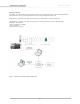
SETUP HDL-32E User’s ManuaI This section describes the standard set up assuming you are connecting the sensor to a standard computer or laptop and mounting the sensor on a vehicle. For other connections and mounting locations, please contact Velodyne for technical assistance. The standard setup involves: 1. Unpacking the shipping case contents. 2. Securely mounting the sensor base to a vehicle or other scanning platform. 3. Connecting power to the sensor. 4.
SET UP HDL-32E User’s Manual Connect Power and Computer The sensor units are commonly used in vehicle applications where standard 12 volt, 2 amp power is readily available. 1. Connect the interface module to power. 2. Connect the Ethernet connector to a standard PC or laptop RJ45 Ethernet port.
USAGE HDL-32E User’s ManuaI The HDL-32E sensor needs no configuration, calibration, or other setup to begin producing usable data. Once the unit is mounted and wired, supplying it power will cause it to start scanning and producing data packets. The quickest way to watch the HDL-32E in action is to use Digital Sensor Recorder (DSR), the viewer software included with the unit.
USAGE HDL-32E User’s ManuaI Alternatively, the calibration data can be found in the included db.xml file found on the CD included with the HDL-32E. The calibration data for vertCorrection is the vertical correction angle for each laser, as viewed from the back of the unit and stated in degrees. Positive values have the laser pointing up and negative values have the laser pointing down.
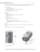
USAGE HDL-32E User’s ManuaI External GPS Time Synchronization The HDL-32E can synchronize its data with precision GPS-supplied time pulses to enable users to ascertain the exact firing time of each laser in any particular packet. This capability requires a GPS receiver generating a sync pulse and the $GPRMC NMEA record over a dedicated RS-232 serial port. The output from the GPS receiver is connected to the HDL-32E via the user interface box.
USAGE HDL-32E User’s ManuaI The images below show the GPS receiver included with the HDL-32E.
USAGE HDL-32E User’s ManuaI Packet Format and Status Byte for GPS Time Stamping The 6 extra bytes at the end of the HDL-32E data packet are used to report GPS timing. For every packet, the last 6 bytes are formatted as follows: 4 bytes: 32 bit unsigned integer time stamp. This value represents microseconds from the top of the hour to the first laser firing in the packet. 2 bytes: blank Time Stamping Accuracy Rules The following rules and subsequent accuracy apply for GPS time stamping: 1.
USAGE HDL-32E User’s ManuaI Laser Firing Sequence The laser firing order is the same as the order in the Ethernet packet. The most downward laser fires first, followed by the interleaved firings from the lower and upper “banks” of 16 lasers, as follows: Firing order DSR # Vertical angle 1 0 -30.67 2 1 -9.33 3 2 -29.33 4 3 -8.00 5 4 -28.00 6 5 -6.66 7 6 -26.66 8 7 -5.33 9 8 -25.33 10 9 -4.00 11 10 -24.00 12 11 -2.67 13 12 -22.67 14 13 -1.33 15 14 -21.
TROUBLESHOOTING HDL-32E User’s ManuaI Use this chart to troubleshoot common problems with the HDL-32E. Problem Resolution Unit doesn’t spin Verify power connection and polarity. Verify proper voltage — should be between 9 and 32 volts drawing a minimum of one amp. Inspect the fuse in the interface module. Replace if necessary. Unit spins but no data Verify Ethernet wiring. Verify packet output using another application (e.g. EthereallWireshark). Verify network settings.
S P E C I F I C AT I O N S Laser: Sensor: Mechanical: Output: HDL-32E User’s ManuaI • Class 1 - eye safe • 905 nm wavelength • Time of flight distance measurement • Measurement range 70 m (1 m to 70 m) • 32 laser/detector pairs • +10.67 to -30.67 degrees field of view (vertical) • 360 degree field of view (horizontal) • 10 Hz frame rate • Operating temperature, -10° C to +60° C • Storage temperature, - 40° to 105° C • Accuracy: <2 cm (one sigma at 25 m) • Angular resolution (vertical) ~1.
A P P E N D I X A : D I G I TA L S E N S O R R E C O R D E R ( D S R ) HDL-32E User’s ManuaI Digital Sensor Recorder (DSR) DSR is a windows-based 3D point cloud visualization software program designed for use with the HDL-32E. This software is an “out of the box” tool for the rendering and recording of point cloud data from the HDL unit. You can develop visualization software using the DSR as a reference platform.
APPENDIX A HDL-32E User’s ManuaI Once the input of streaming data has been confirmed through the live playback feature, click on the Record button and the program will request the name and location for the pcap file to be created. Recording will begin immediately once the file information has been entered. Click on the Record button again to discontinue the capture. One can string multiple recordings together on the same file by performing the Record function repeatedly.
APPENDIX A HDL-32E User’s ManuaI DSR Key Controls Zoom: Z = Zoom in Shift, Z = Zoom out Z Axis Rotation: Y = Rotate CW Shift, Y = Rotate CCW X Axis Rotation: P = Rotate CW Shift, P = Rotate CCW Y Axis Rotation: R = Rotate CW Shift, R = Rotate CCW Z Shift: F = Forward B = Back X Shift: L = Left H = Right Y Shift: U = Up D = Down Aux.
A P P E N D I X B : H D L - 3 2 E S A M P L E D ATA PA C K E T S HDL-32E User’s ManuaI Data Packet Format The HDL-32E outputs two UDP Ethernet packets — a data packet containing laser firing data located on Port 2368 and a positioning packet which contains GPS and positioning data located on Port 8308. The packet at Port 2368 contains a header, a data payload of firing data and status data. Data packets are assembled with the collection of all firing data for twelve laser firing sequences.
APPENDIX B HDL-32E User’s ManuaI User Datagram Protocol (UDP) Ethernet Data Packet Format: HDL-32E (Port 2368) Start identifier OxEEFF 2 mm increments (0 = no return within 100 m) Blank Blank Figure B1.
APPENDIX B HDL-32E User’s ManuaI Positioning Packet Using outputs from onboard gryrometers and 2-axis accelerometers, orientations shown below in Figure B2, the positioning ethernet Packet provides motion data (rotational and acceleration) for the stationary base of the HDL-32E unit. See the User Datagram Protocol (UDP) Positioning Ethernet Packet Format: HDL-32E, Figure B3, for interpretation of data output. I 0 degrees Figure B2.
APPENDIX B HDL-32E User’s ManuaI 234 Figure B3.
APPENDIX B HDL-32E User’s ManuaI Time Stamp: “7c bd 9c 91” 2442968444(919cbd7c hex)usec = 2442.9sec Time stamp from the head of the hour in usec. NMEA Sentence: “$GPRMC, 214042, A, 3708.3087, N, 12139.5146W, 000.0, 000.0, 160311, 014.
APPENDIX B HDL-32E User’s ManuaI Ethernet Packet Example Captured via Wireshark.
A P P E N D I X C : C O O R D I N AT E C A L C U L AT I O N A L G O R I T H M S A M P L E C O D E HDL-32E User’s ManuaI Coordinate Calculation Algorithm Sample Code After removing all the correction parameters except vertical correction, the calculation code is: firingData::computeCoords(guintl6 laserNum, boost::shared_ptr db, GLpos_t &pos) { guintl6 idx = laserNum % VLS_LASER_PER_FIRING; boost::shared_ptr cal = db->getCalibration(laserNum); if (data->points[idx].
A P P E N D I X D : C A L I B R AT I O N A N D O R I E N TAT I O N HDL-32E User’s ManuaI Calibration and Orientation There are six axes of variation when determining the exact location of any given laser firing for the HDL-32. The axes are x, y, z, along with rotational, horizontal, and vertical angles. X, Y, Z. Both x and y offsets are zero and are calculated from the centerline of the device.
A P P E N D I X D : C A L I B R AT I O N A N D O R I E N TAT I O N HDL-32E User’s ManuaI [ 24 ]
Velodyne LiDAR, Inc. 345 Digital Drive Morgan Hill, CA 95037 408.465.2800 voice 408.779.9227 fax 408.779.9208 service fax www.velodynelidar.com Service Email: lidarservice@velodyne.com Sales Email: lidar@velodyne.com All Velodyne products are made in the U.S.A. Specifications subject to change without notice Other trademarks or registered trademarks are property of their respective owner.