impact SERIES IMPACT .. 10 IMPACT .. 12 IMPACT ..
IMPORTANT SAFETY INSTRUCTIONS A AS Caution To reduce the risk of electric shock, do not remove cover (or back). No user-serviceable parts inside. Refer servicing to qualified service personnel. The lightning flash with arrowhead symbol is intended to alert the user to the presence of uninsulated "dangerous voltage" within the product's enclosure that may be of sufficient magnitude to constitute a risk of electric shock to persons.
TABLE OF CONTENTS ,..-",_?"''''~ _~ 4 ~ ~ _ .... ~ =~....., 4 ~".. _ _ . " ". . Congratulations .1 Installation .2 .. , Rear Panel Connections .5 Crossovers . . . . . . .6 Interconnect Cables .9 Care of Your Subwoofer .9 Protection Circuitry ... .. 9 Troubleshooting and Service .10 ... .11 Velodyne Products .12 Specifications WWW.VELODYNE.
CONGRATULATIONS Congratulations on your purchase of a Velodyne Impact subwoofer system. This system represents the state-of-the-art in home audio reproduction and will provide you with years of listening pleasure when properly used and cared for. Read and follow this instruction manual to ensure safe and proper system connection and operation. Caution! Please observe the following instructions to insure safe and proper system operation.
Placement The first step in installing your new Impact sub is to determine where it will be placed in the room. Unpack the system carefully and use the following guidelines in order to find the best room placement option. True subwoofers operate at extremely low frequencies which are primarily omni-directional. Keep in mind that frequency response and output level can be drastically influenced by placement, depending on the acoustic properties of the listening room.
To alleviate this condition, we recommend the following steps: 1) If using line level jacks, BOTH THE LEFT AND RIGHT INPUT SHOULD ALWAYS BE USED never use just the left or just the right input. If the subwoofer's input comes from the LFE channel of your receiver, use the included "Y" splitter to supply the single input to both connectors for the Left and Right subwoofer inputs.
Low-pass Crossover - 50 to 200 Hz As noted above, all inputs sum the left and right channels together, with the resulting signal passing through an adjustable low-pass crossover before being amplified. The crossover control allows you to adjust the upper limit of the subwoofer's frequency response from 50 to 200 Hz. The subwoofer's response will begin rolling off above the frequency you set this control to.
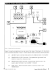
REAR PANEL CONNECTIONS 3 2 4 PHASE LOW PASS FREQUENCY 80HZ SUBWOOFER VOLUME no' 'Y-!" . .' SOHZ 200HZ MIN MAX 5 1 6 Velodyne 7 SERIAL # LABEL INPUT VOLTAGE @ WARNING: TOREOUCE THE RI$K OF FIRE OR ELECTRIC SHOCK. DO NOT EXPOSE A,"I:'P~A.NC.EU.T.~o.OR~mREA AVIS: ( @ EIri\ m @ RED: STANDBY GREEN: ON [[0 0J HJ ~ = 6 FUSE TYPE TlAL2S0V FOR llSV TO SAL 2S0V FOR 230V RISQUE DE CHoe ELECTRIQUE·NE PAS OUVRIR Figure 1.
(5) VOLUME LEVEL knob - Use this knob to adjust the output level of the subwoofer. (6) LOW-PASS CROSSOVER - Use this knob to select the high-frequency range at which you wish to cut-off the signal to the subwoofer. (7) Power indicator - Red: Unit is in standby mode. Green: Unit is in operation mode. (automatically turns to STANDBY mode if no signal for eight minutes) ~~ CROSSOVERS .-,.-,. -"'" ..... -~ , ~..,. .,...,......~~~'--~. ~ - -,-"--- ~_ - - -~. ... _-..11'-'"""'"-"" ~ ...
SUBWOOFER OUTPUT JACK AMPLIFIER PHASE SPEAKER LEVEL ® O· LOW PASS FREQUENCY ·080~.. • LFE IN / SUBWOOFER VOLUME '0''. •• • •• 50HZ 200HZ •• MIN MAX Velodyne SERIAL # LABEL @ @ WARNING: TO REDUCE THE RISK OF FIRE OR ELECTRIC SHOCK. DO NOT EXPOSE @ • THI:APC.A.Ne.EU.T.~O.ORM~TURE A AVIS: RISQUE OE eHoe ."EeTRIQUE"'. PAS OUYRIR ( r:J0I '\:::!/ INPUT VOLTAGE EIti\ m lID @ ~ 8 RED: STANDBY GREEN: ON ~ rtf o I FUSE TYPE: TlAL 2S0V FOR 11SV TO.SAL2S0V FOR 230V 11sn3OV ........
SUBWOOFER OUTPUT JACK ® I I I AMPLIFIER PHASE LlLe INPUT rirn"!J~~~ SUBWOOFER VOLUME lOW PASS FREQUENCY ~ . . . ·0· 0. . . . 80HZ ~ .. LFE IN 50HZ .. .. 200HZ . MIN MAX Velodyne SERIAL # LABEL WARHlHG: TO REDUCE THE IUSK Of FIRE OR ELECTRIC SHOCK. DO NOT EXPOSE THIS APPl....NCE TO RAIN OR MOIST\JRE. eE~ IJi:::'I. \::£) AVIS: RISQUE DE CHOC ElECTRIQUE-NE PAS OUVRIR """"lE ..SULOT!OI<·WlIC" SVI""CINGunONlY II;>[NTIC.C.E.UO'CE.IUIT .....n. ::::~:::"., CANICS'" STD.C22.2 No.
INTERCONNECT CABLES When installing your new Velodyne subwoofer using the line level connections, you should always use shielded phono cables. There are many high quality cables available today. It is recommended that you keep the length of cable as short as possible to avoid any potential noise problems. When using speaker level connections, use a high quality speaker cable that mates well with the connectors.
TROUBLESHOOTING AND SERVICE Before seeking service for your amplifier or subwoofer, please re-check all systems. Following is a simple troubleshooting guide to assist you. 1. 2. 3. 4. 5. Verify that the unit is plugged in and power outlet used is active. Is the power switch on? Is the unit receiving an input signal from your source? Have all controls [volume, crossover, phase, etc.) been properly set? If the unit has been running at high levels, one of the protection circuits may be engaged.
SPECIFICATIONS SPECIFICATIONS IMPACT- Mini IMPACT-l0 IMPACT-12 '?'loafer 6Y' (165 cm) active (5 N pis10n diameter) & 8N (ZO.3 em) passive (6.5 N pi5lon diameter) lO N(Z4.5 em) forward nring (8 Zo'" pi5lon diameter) lZ N(305 cm) foward nring (9 7'" pi5lon diameter) Amplifier.
.. " VELODYNE PRODUCTS 230V 120V DD® Series 00-10 00-12 00-15 00-18 Digital Drive 1812 Signature Edition DLSTM"R Series OLS-3500R OLS-3750R OLS-4000R OLS-5000R DPSTM Series OPS-10 OPS-12 Impact Series Impact- Mini Impact-10 Impact-12 MicroVee™ MiniVee® MiniVee® 10 WWW.VELODYNE.
FOR YOUR RECORDS. Date Purchased _ Dealer-----------------------------------Serial # _ *NOTE: Please complete and return your warranty card within ten (10J days or Register. . . ON LINE . . . It's faster . . . and easier www.llelodyne.com LIMITED WARRANTY· u.s. AND CANADA ONLY VELODYNE ACOUSTICS, Inc. ("VELODYNE") warrants all electronics for a period of three years, drivers for a period of five years, and full range speakers for a period of five years.
Velodyne Acoustics, Inc. 345 Digital Drive Morgan Hill, CA 95037 408.465.2800 voice 408.779.9227 fax 408.779.9208 service fax www.velodyne.com Service E-mail: service@velodyne.com Product E-mail: help@velodyne.com Technical E-mail: techhelp@velodyne.com ® 63
return address place stamp here Velodyne Acoustics, Inc.
Velodyne 1. OWNERS REGISTRATION Name _ _ _ _ _ _ _ _ _ _ _ _ _ _ _ _ _ _ Street _ City _ _ _ _ _ _ _ _ _ _ _ _ _ _ _ _ _ _ _ _ State Zip _ Country _ _ _ _ _ _ _ _ _ _ _ _ _ _ _ Phone _ E-mail 2. Model #_ _ _ _ _ _ _ _ _ _ _ _ _ _ _ S/N _ Date Purchased _ _ _ _ _ _ _ _ _ _ _ Purchase Price 3. _ Dealer Name _ _ _ _ _ _ _ _ _ _ _ _ _ _ City _ State _____________ Country 4. Zip Comments: 5. Would you like to be notified of new Velodyne products or special promotions via email? 6.
Velodyne Extended Product Warranty Velodyne products are now backed by one of the strongest warrantiea in the industry. Th is new warranty supercedes the one found in your manual. The warranty on drivers has been extended from two years to five years the warranty on all amplifiers and electronics has been extended from two years to three years and the warranty on full-range speakers remains the same at five years.