OpTIMUM SERIES QPTIMUM.. 8 QPTIMUM.. 10 QPTIMUM..
IMPORTANT SAFETY INSTRUCTIONS A ~ CAUTION A ~ ~ \0' Caution To reduce the risk of electric shock, do not remove cover (or back). No user-serviceable parts inside. Refer servicing to qualified service personnel. The lightning flash with arrowhead symbol is intended to alert the user to the presence of uninsulated "dangerous voltage" within the product's enclosure that may be of sufficient magnitude to constitute a risk of electric shock to persons.
TABLE OF CONTENTS Congratulations . Installation . · · Front Panel Features . · Rear Panel Connections . 1 3 5 · 7 Rear Panel Connections - Detailed Explanation . . . · 9 Interconnect Cables . . . . .. ... .. . . · 10 Usage ... ... . . . .. .. 11 Care of Your Subwoofer . . · 15 Troubleshooting and Service . . · 15 Specifications . . . . .. . . · 16 Velodyne Products . . . . . .. . . · 18 WWW.VELODYNE.
CONGRATULATIONS Congratulations on your purchase of a Velodyne Optimum subwoofer. This system represents the state-of-the-art in low frequency reprodL!ccion. Please, read and follow the instructions below to insure safe and proper system operation. Warning! To prevent fire or shock hazard, do not expose this equipment to rain or moisture. To avoid electrical shock, do not open speaker enclosure or amp chassis cover. Please observe all warnings on the equipment itself.
Prepare for Installation Your new Velodyne subwoofer provides for a number of installation options. Read all of the installation information below in order to determine which installation option is best for your system. Remember to perform all installation procedures with system power turned off to prevent possible damage. Placement The first step in installing your new Optimum sub is to determine where it will be placed in the room.
INSTALLATION Inputs Your new subwoofer is equipped with speaker-level and line-level inputs. Use the LINE LEVEL jacks when connecting your subwoofer to a pre-amp, signal processor [such as LFE out], linelevel crossover, or receiver with pre-amp level outputs. When using the line level jacks, some receivers may not provide enough signal to have the unit's auto-on feature operate properly. Additionally, this lack of signal may also cause the subwoofer to produce less output than it is capable of.
Phase Adjustment· 0°/90°/180°/270° This control allows you to change the phase of the subwoofer's output signal to correct for any possible mismatch and resulting cancellation between the subwoofer and your main speakers/amplifier. To adjust, simply listen to the system with music playing, then depress the various phase switches on the remote control and listen for a change in mid-bass frequency output. The correct position will have a greater amount of apparent mid-bass frequency output.
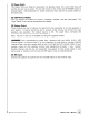
FRONT PANEL FEATURES Figure 1. Optimum Front Panel Features Figure 1 shows the features on the front panel of the Optimum. WWW.VELODYNE.
(1) Power Switch This button forces your Optimum subwoofer into standby mode. The numeric LED shuts off and the sub puts out no power. The sub will remain in this mode until the POWER button is pressed again. To fully deactivate (i.e. power button) the sub, use the main power switch on the back panel. (2) LED Numeric Display This LED supplies information on volume, crossover, presets, and other information. The "Light" button on the remote deactivates this display.
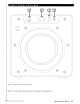
REAR PANEL CONNECTIONS @ @ @ 80 Hz @ @ Vel odyn e :@: LOW-PASS CROSSOVER DIRECT @ @ 40 Hz UP • VOLUME DOWN • POWER AUTO ON/OFF @ @ ACTlVE~ ON @ @ R I IR INPUT 0 L ~~ OUTPUT @ ~0 12V TRIGGER OFF INPUT '-LFE SPEAKER LEVEL INPUT @ + 117V60Hz 8A @ INACTIVE R L + @ @ @ A~rel~~~~·.A AVI s: @ @ '6~~~~gTJZ~~~~~MtS:x?6~~E THIS APPliANCE TO RAIN OR MOISTURE. RISQUE DE CHOC ELECTAIQUE-NE PAS OUVAIA SERIAL # LABEL VELODYNE ACOUSTICS. INC. @ Figure 2.
Following are brief descriptions of the connections described in Figure 2. More detail on these connections can be found in the next section. (1) LOW-PASS CROSSOVER Use this knob to select the frequency above which you wish to roll off the signal to the subwoofer. When the knob is turned all the way to the left, the Subwoofer Direct feature is invoked and the subwoofer plays all frequencies up to 200 Hz.
REAR PANEL CONNECTIONS· DETAILED EXPLANATION Your new subwoofer is equipped with both speaker-level and line-level inputs. Use the RCA/Phono type "INPUT" jacks when connecting your subwoofer to a pre-amp, signal processor, or line-level crossover. The "SPEAKER LEVEL INPUT" jacks connect directly to the speaker outputs of an integrated amplifier or receiver. Your amplifier section will notice no additional loading effects when you use these inputs because of their high impedance.
A Word About Your Receiver's Crossover and the Velodyne Optimum Subwoofer Crossover Your Velodyne Optimum subwoofer is designed to operate using the full range audio signal for input when using the built-in crossover (controlled by the dial on the back panel). Many home theater processors/receivers (Dolby Digital®, DTS®, THX®) have a "subwoofer out" jack that performs this same function and are designed to be used with a powered subwoofer.
USAGE This section addresses day-to-day usage of your Optimum subwoofer. Remote Control Figure 3 shows the remote control, enabling you to easily choose whatever listening mode you desire. NOTE: The Optimum remote can be attached magnetically to the back of the subwoofer in the upper left hand corne~ Figure 3. Remote Control POWER This button forces your Optimum unit into standby mode. The woofer will not play and the LEO will turn off.
EQ This button automatically EQs the subwoofer using a 6-band internal parametric equalizer. To use this feature, first plug the supplied microphone into the Mic Input jack on the front panel of the subwoofer and place the mic on its stand and in your preferred listening position. Then, by pressing EQ on the remote, the subwoofer emits 12 "sweep tones" that cover the frequencies between 20 and 150 Hz.
PRESETS There are four presets, consisting of Movies, R&B - Rock, Jazz - Classical, and Games. As a preset is chosen, the LED display shows the selected preset: P1, P2, P3 or P4. The presets provide the following characteristics for bass reproduction: Movies: [P1) Maximum output and impact for explosions and other action adventure movie content. R&B - Rock: [P2) Provides the driving bass found in today's rock music. Jazz - Classical: [P3) The tightest, cleanest, lowest distortion bass.
Each preset has its own characteristics with respect to subsonic filter, volume differential and a single equalizer [EQ) in order to optimize the listening mode for the preset.
CARE OF YOUR SUBWOOFER Do not use any harsh detergents or chemicals to clean the cabinet. Abrasives, detergents, or cleaning solutions will damage the finish on the cabinet. We recommend using a damp cloth to clean the front, back and sides. During normal conditions, the subwoofer may be left on continuously without any problems. If you plan to leave the unit unused for an extended period of time, we recommend that you turn off the subwoofer by the master power switch on the rear panel.
SPECIFICATIONS Specifications Optimum·8 Optimum.10 Optimum·12 8" forward firing 10" forward firing 12" forward firing [6.
FOR YOUR RECORDS. Date Purchased, _ Dealer _ Serial # _ * NOTE: Please complete and return your warranty card within ten {10J days or Register. . . ON LINE . . . It's faster . . . and easier www.velodlJne.com LIMITED WARRANTY· U.S. AND CANADA DNLY VELODYNE ACOUSTICS, Inc. ("VELODYNE"j warrants all electronics for a period of three years, drivers for a period of five years, and full range speakers for a period of five years.
VELODYNE PRODUCTS 120V DD® Series 00-10 00-12 00-15 00-18 Digital Drive 1812 Signature Edition DEQ-R Series OEQ-8R OEQ-10R OEQ-12R OEQ-15R DLSTM"R Series OLS-3500R OLS-3750R OLS-4000R OLS-5000R Impact Series Impact- Mini Impact-10 Impact-12 230V MicroVee™ MiniVee® MiniVee® 10 Optimum Series Optimum-8 Optimum-10 Optimum-12 SubContractor™ Series SC-1250 SC-10 SC-12 SC-15 SC-IW SC-IF/IC SC-600 Amp SC-600 IW SC-600 IFIIC DD® Series 00-10 00-12 00-15 00-18 Digital Drive 1812 Signature Edition CHT-Q Ser
Velodyne Acoustics, Inc. 345 Digital Drive Morgan Hill, CA 95037 408.465.2800 voice 408.779.9227 fax 408.779.9208 service fax www.velodyne.com Service E-mail: service@velodyne.com Product E-mail: help@velodyne.com Technical E-mail: techhelp@velodyne.com @ 6:HPT R~ A Aums WWW.VELODYNE.
Velodyne 1. OWNERS REGISTRATION Street Name _ _ _-=- _ City _ _ _ _ _ _ _ _ _ _ _ _ _ _ _ _ _ _ _ State Zip _ Country _ _ _ _ _ _ _ _ _ _ _ _ _ _ Phone _ E-mail 2. 3. Model #_ _ _ _ _ _ _ _ _ _ _ _ _ _ S/N _ Date Purchased _ _ _ _ _ _ _ _ _ _ _ Purchase Price _ Dealer Name _ _ _ _ _ _ _ _ _ _ _ _ _ _ City _ State _ _ _ _ _ _ _ _ _ _ _ _ Country 4. Zip Comments: 5. Would you like to be notified of new Velodyne products or special promotions via email? 6.
return address place stamp here Velodyne Acoustics, Inc.
Velodyne Extended Product Warranty Velodyne products are now backed by one of the strongest warrantiea in the industry. Th is new warranty supercedes the one found in your manual. The warranty on drivers has been extended from two years to five years, the warranty on all amplifiers and electronics has been extended from two years to three years and the warranty on full-range speakers remains the same at five years.